- English
- French
- German
- Portuguese
- Spanish
- Russian
- Japanese
- Korean
- Arabic
- Greek
- German
- Turkish
- Italian
- Danish
- Romanian
- Indonesian
- Czech
- Afrikaans
- Swedish
- Polish
- Basque
- Catalan
- Esperanto
- Hindi
- Lao
- Albanian
- Amharic
- Armenian
- Azerbaijani
- Belarusian
- Bengali
- Bosnian
- Bulgarian
- Cebuano
- Chichewa
- Corsican
- Croatian
- Dutch
- Estonian
- Filipino
- Finnish
- Frisian
- Galician
- Georgian
- Gujarati
- Haitian
- Hausa
- Hawaiian
- Hebrew
- Hmong
- Hungarian
- Icelandic
- Igbo
- Javanese
- Kannada
- Kazakh
- Khmer
- Kurdish
- Kyrgyz
- Latin
- Latvian
- Lithuanian
- Luxembou..
- Macedonian
- Malagasy
- Malay
- Malayalam
- Maltese
- Maori
- Marathi
- Mongolian
- Burmese
- Nepali
- Norwegian
- Pashto
- Persian
- Punjabi
- Serbian
- Sesotho
- Sinhala
- Slovak
- Slovenian
- Somali
- Samoan
- Scots Gaelic
- Shona
- Sindhi
- Sundanese
- Swahili
- Tajik
- Tamil
- Telugu
- Thai
- Ukrainian
- Urdu
- Uzbek
- Vietnamese
- Welsh
- Xhosa
- Yiddish
- Yoruba
- Zulu
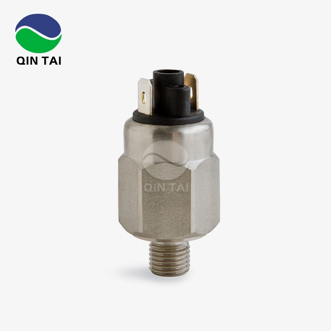
Detailed explanation of the position and working principle of the urea pump sensor
A Urea dosing pressure sensor is an important part of current SCR (Selective Catalytic Reduction) systems because it checks the pressure of the diesel exhaust fluid directly in the dosing circuit. This sensor is placed between the dose pump and the injection nozzle. It regularly checks the pressure and sends feedback to the engine control unit in real time. Accurately measuring pressure lets the system change the amount of urea that is delivered, which makes sure that the best NOx reduction happens while still meeting strict emission standards like EPA 2010 and Euro VI. If the sensor finds pressures that aren't within the target ranges, it starts corrective actions that keep emissions in line and keep downstream parts from getting damaged.

Understanding the Urea Pump Sensor: Position and Importance
Physical Location Within the SCR System
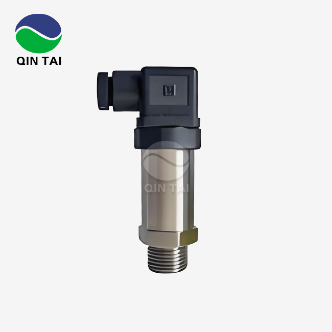
Most of the time, the pressure sensor is attached directly to the body of the dosing pump or along the high-pressure line that connects the pump to the injector. Putting the sensor close to the pump cuts down on pressure signal lag and the chance of measurement mistakes caused by drops in line pressure. When engineers build aftertreatment systems, they have to figure out the best place to mount the system so that it doesn't expand or contract with temperature changes and is easy to get to for upkeep.
In heavy-duty diesel uses, the sensor is often built into the pump section as a single unit. This cuts down on the number of places where it could connect to other parts and leak. OEM makers are liking this combined design more and more because it makes installation easier and makes the system more reliable during mass production.
Critical Role in Emission Control
How quickly the control unit reacts to changes in engine load and air conditions depends on where the sensors are placed. Hydraulic delays can lead to dose errors when the sensor is too far from the pump, which can mean either too much urea use or not enough NOx conversion. Studies by the International Council on Clean Transportation show that during short engine runs, even 0.2-bar measuring mistakes can cause NOx emissions to rise by 8–12%.
When choosing a provider, procurement managers who are looking at SCR systems should put the placement of sensors at the top of their list of priorities. Closed-loop control algorithms can keep dosing accuracy within ±5% across the full engine working range if the pressure sensor is placed correctly. This is necessary to pass emission certification tests and avoid costly compliance penalties.
Interaction With Other System Components
Along with the temperature sensors, NOx sensors, and the dose control valve, the pressure sensor forms a planned plan to lower emissions. The control unit uses data from the pressure sensor to stop urea input when exhaust temperatures drop below the level needed for the SCR catalyst to activate. This keeps crystallization deposits from building up in the dose system. On the other hand, when there is a lot of work to be done and NOx reduction is needed, the pressure sensor makes sure there is enough supply pressure before telling the control unit to increase the input rates.
This teamwork between multiple sensors is especially important in generator set situations where load changes quickly. The pressure sensor gives the control unit instant input that it needs to change the dosing rates within 200 to 500 milliseconds. This stops both under-dosing, which causes emission spikes, and over-dosing, which wastes fluid and lets ammonia slip.

Working Principle of the Urea Pump Pressure Sensor
Pressure Measurement Technology
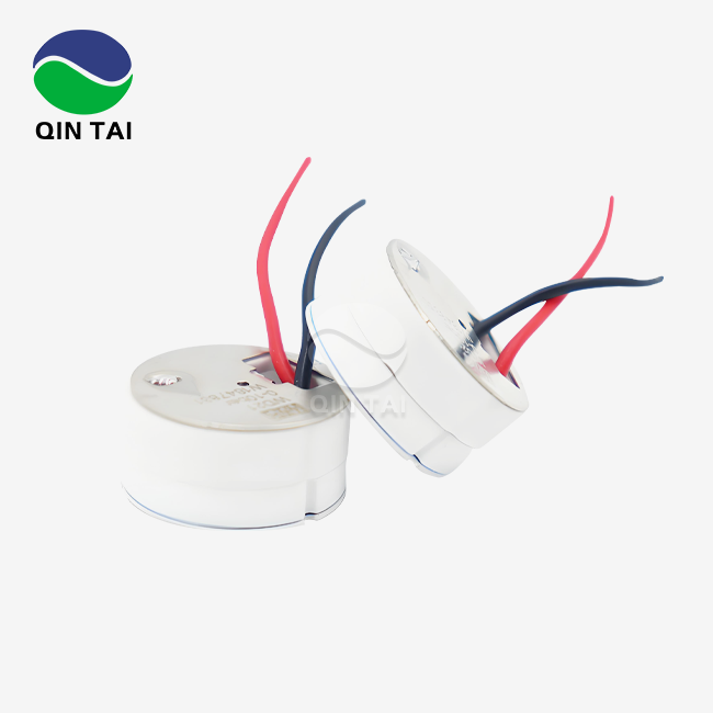
Most Urea dosing pressure sensors use piezoresistive or thin-film strain gauge technology that has been specially modified to work in water-based urea settings. There are changes that can be measured in the electrical resistance of semiconductor elements inserted in the sensing surface when a pressurized urea solution comes in touch with the diaphragm of the sensor. These changes in resistance cause changes in voltage, which are then turned into standard output signs by the sensor's built-in circuit.
Because 32.5% urea solution is toxic, manufacturers have come up with special diaphragm materials and finishes that can handle it. When standard stainless steel sensors are exposed to urea at high temperatures, they break down quickly, which means they fail before they should. Modern sensors have diaphragms that are covered in ceramic or polymer and keep measuring accurately even after 10,000 hours of direct touch with diesel exhaust fluid.
Most measurement ranges are between 0 and 10 bar, but some high-performance systems can work at up to 15 bar to accommodate long input lines or setups with more than one injector. The sensor's accuracy specs say that it should be within ±0.1 bar of the operating range, which is fine for apps that need to be precise with emissions.
Signal Processing and Communication
Continuous voltage readings from analog pressure sensors usually range from 0.5V at zero pressure to 4.5V at maximum rated pressure. The engine control unit takes this voltage data at rates of 100 to 1000 Hz, which lets it keep an eye on the pressure in real time during injection cycles. This analog method is popular in commercial car uses that need to save money because it is simple and reliable.
Microprocessors inside digital sensors turn pressure readings into digital standards like CAN bus or LIN communication. These smart sensors have many benefits: they can check themselves for problems, fix mistakes caused by weather, and send extra information like sensor identification codes and fault status. Digital sensor designs are very helpful for systems that need to be able to diagnose things very well, especially those that serve various aftertreatment devices.
When deciding between analog and digital sensors, you have to weigh the original cost, the ability to diagnose problems, and the complexity of the system. We've seen that OEMs that make a lot of commercial vehicles choose analog sensors because they are more reliable and cost less per unit. On the other hand, premium equipment manufacturers like digital sensors because they have better diagnostic features and are easier to connect to advanced telematics systems.
Closed-Loop Dosing Control
The pressure sensor makes it possible for complex closed-loop control methods to keep improving the delivery of urea. As soon as the control unit tells the dose pump to start working, it checks the signal from the pressure sensor to make sure the system pressure gets to the right level. If the recorded pressure is less than the goal, the control unit speeds up the pump or makes it run for longer. On the other hand, if the pressure goes above the goal, the control unit lowers the output of the pump to stop over-pressurization, which could damage seals or cause unnecessary fault codes.
In cold-start conditions, when the viscosity of the urea solution rises a lot, this feedback system is especially helpful. The control unit checks for high viscosity conditions by using pressure input and changes the pump settings accordingly. This makes sure that dosing works reliably even when the temperature outside gets close to -11°C, which is the freezing point of diesel exhaust fluid.
When the engine is running in a steady state, the control unit pulse-width modulates the dose pump to keep the system pressure within a narrow band. The pressure sensor lets the control unit see if the pressure drops between injections, which could mean that there are leaks in the dose circuit. This monitoring feature helps repair teams find parts that aren't working right before the whole system breaks down.

Troubleshooting and Maintenance of Urea Pump Pressure Sensors
Common Failure Symptoms
Pressure sensor problems, particularly with the Urea dosing pressure sensor, usually show up in a number of ways that can be seen. When the control unit finds pressure readings that aren't in the normal range, it often turns on warning lights on the dashboard, like the failure indicator lamp or special SCR system alerts. Diesel exhaust fluid use may go up as the system tries to make up for what it thinks is an inadequate dose, or the engine may have less power when the control unit goes into "limp mode" to protect emission system parts.
Diagnostic trouble codes tell you a lot about the health of a sensor. If you see codes for open or short circuits, it means there are problems with the electrical connections. On the other hand, codes for pressure values that don't make sense mean that the sensor element is broken or contaminated. Rather than a sensor element failing, problems that come and go often mean that the connecting pins are corroded or the mounting hardware is loose.
Diagnostic Testing Procedures
As a first step in the troubleshooting process, technicians should check the electrical lines for damage, corrosion, or looseness. By checking the sensor input voltage with a digital voltmeter, we can be sure that the control unit gives the needed 5V reference voltage. Checking the sensor's output voltage while the pump is running helps find out if it sends the right signs when the pressure changes.
By applying known pressures and comparing sensor output to standard values, pressure testing tools made for SCR systems can make sure that sensors are accurate. Comparative testing like this makes it easy to find sensors that have moved out of alignment. Technicians should do these tests with the sensor at room temperature, since changes in temperature can hide problems with accuracy when testing in a cold bench.
Systematic fixing is needed to tell the difference between sensor breakdowns and other problems with the system. A pressure sensor that reports low pressure could mean that the sensor itself is broken, but it could also mean that the dosing pump is weak, the filter is clogged, or there is a leak in the supply line. Putting in a temporary reference sensor along with the suspect sensor is the only way to be sure that the suspect sensor is accurate.
Preventive Maintenance Strategies
Visually checking the mounting points of sensors for signs of leakage, checking the electrical connections for corrosion, and making sure the sensors are securely installed should all be part of regular inspection plans. Crystallized urea contamination is a regular problem that needs to be fixed. Using clean water to run regular system cleaning processes helps keep crystals from building up on sensor diaphragms, which extends their useful life.
Regular checks of the calibration make sure that the measurements stay accurate. Most sensors can't be calibrated in the field, but comparing results to reference tools can tell you which sensors are getting close to the end of their useful life before they cause problems. By writing down sensor output numbers during regular upkeep, you can see how they have changed over time.
Keeping sensors away from high temperatures makes their useful life much longer. Adding thermal shielding around sensor bodies or moving sensors away from heat sources in exhaust systems can help reduce thermal stress in places where the environment is tough. These safety steps are especially helpful for setups of generator sets where the equipment works in unconditioned areas that can change temperatures by more than 80°C.
Selection Criteria and Comparison of Urea Dosing Pressure Sensors
Key Technical Specifications
The level of accuracy needed depends on the purpose. Agricultural equipment with mostly steady engine loads can work with sensors that are accurate to within 0.2 bars, but heavy-duty cars that often have to deal with changing conditions need specs that are even more exact, at least 0.1 bars. When the load on an application changes quickly, response time becomes very important. Sensors with reaction times less than 50 milliseconds let control systems change dosing rates fast enough to keep emissions from going off when gears are changed or when the vehicle speeds up suddenly.
Chemical compatibility goes beyond the wet materials on the sensor and includes O-rings, glue, and potting solutions. Diesel exhaust fluid has chemicals added to it that can damage polymer materials that weren't made to be exposed to urea. If you choose sensors that are approved for long-term urea contact, you can avoid early failures caused by seal degradation or housing rust. With sensors rated for 20G acceleration across the frequency range of 10-2000 Hz, durability requirements should take into account the vibration environment typical of engine-mounted uses.
Analog Versus Digital Technology
Analog sensors are still the most common choice for standard aftertreatment tasks because they are easy to use, have a history of stability, and are cheap to produce in large quantities. There are only three electrical connections that these sensors need to work, and they connect straight to normal analog input channels on engine control units. Their simple design cuts down on failure spots and makes troubleshooting easier while they are being used in the field.
Digital Urea dosing pressure sensors are better in systems that need to do complex troubleshooting or work with more than one emission control device. Being able to send sensor identification data lets control units recognize new sensors instantly, without having to be programmed by hand. Built-in self-test processes find problems inside the system before they cause dosing mistakes. This makes the system more reliable and cuts down on downtime. Digital sensors have a higher starting cost, but they are worth it in situations where they can diagnose problems quickly and avoid replacing parts that aren't needed. This is called "total cost of ownership."
Comparative Brand Analysis
The best sensor makers bring different strengths to the market. Bosch has a strong name for high-volume car applications. Their sensors are designed to be cost-effective while still meeting the high quality standards needed by OEMs. Continental mainly makes integrated units that have pressure sensors, temperature sensors, and computer controls all in one small package that is good for installations with limited room.
Delphi Technologies focuses on making sensor designs that are specifically made for heavy-duty industrial vehicles. These designs have extra longevity features that deal with the harsh vibration and temperature conditions of these applications. Siemens provides industrial-grade dependability to generator sets and fixed power uses that need sensors that are more durable than those used in cars because of long repair intervals and harsh environmental conditions.
People who work in procurement should look at guarantee terms to see how confident the maker is in their products. Standard guarantees last between 12 and 24 months, but some makers offer longer warranties for uses that need to be very reliable. Due to recent lack of parts around the world, supply chain resilience has become more important. Manufacturers with various production sites and a variety of sources for parts show that they can provide a steady supply for long-term partnerships.

SENSOR+TEST, June 9 – 11, 2026
We look forward to your visit,warmly welcome to our booth 1-634!
Get your free ticket online now:
https://www.sensor-test.de/service/ticket/?52790
Installation Guide and Best Practices for Urea Pump Sensors
Pre-Installation Considerations
Checking for compatibility is the first and most important step in installing sensors. Making sure that the electrical connector on the sensor matches the one on the car wiring avoids installation delays and damage that could happen from making connections that are too tight. Making sure that the thread specs fit the mounting boss makes sure that the sealing and force are applied correctly. The temperature limit has to be higher than the highest temperature that can be predicted where it will be mounted, taking into account both the outside temperature and heat transfer from nearby exhaust parts.
Special care needs to be taken with environmental factors that are unique to industrial settings. When used on construction equipment that is exposed to dust, sensors with sealed connections and extra safety boots are more useful. For marine generator uses, sensors need to be more resistant to rust so they can handle being exposed to salt spray. Mining equipment needs sensors that can work even when they are vibrating constantly and could be hit by objects while working in rough terrain.
Step-by-Step Installation Process
To begin, make sure the surface you'll be putting the sensor on is clean and free of any old sealant or other dirt that could get in the way of proper seating. Thread sealer that works with urea solution should be put on the sensor threads, but not too much should be used because it could get on the detecting element. Hand-thread the sensor into the mounting boss until you feel resistance. Then, use a calibrated torque wrench to apply the torque number provided by the maker. When you over-torque, you can crack sensor housings or deform sealing surfaces, and when you under-torque, you can create leak paths and measurement mistakes from poor mechanical loads.
After the mechanical fitting is done, connect the electrical harness and make sure the link locks all the way into place. Use the clips or ties that come with the sensor to keep the wires away from heat sources and moving parts so they don't rub against each other. Leave enough of a service loop so that the engine can move without putting too much stress on the link. Apply dielectric grease to connector contacts to protect them from rust even more in sites that will be exposed to water.
Post-Installation Verification
After installation, turn the key a few times to power the control unit and check to see if any error codes show up. When many systems are first turned on, the sensors are automatically recognized and the range is checked. Using diagnostic scan tools to keep an eye on live sensor data while the pump is running proves that the signals are being sent correctly. When you compare pressure readings from controlled pump activation cycles to predicted values, you can be sure that the sensor reacts correctly to changes in pressure.
After electricity proof, leak testing should be done. Running the dose pump while keeping an eye on the sensor fixing area for any fluid leaks makes sure the seal is good. Even small leaks cause urea to slowly crystallize, which hurts the sensor's performance in the long run. Taking care of installation leaks right away saves you money in the long run by avoiding expensive repairs and replacements. By writing down standard sensor values during setup, you can use this information to compare future diagnostic results.
Conclusion
Urea dosing pressure sensors are precise tools that are needed for the SCR system to work and for emissions to be legal. Today's diesel engines can meet stricter environmental rules while still running efficiently thanks to their exact measurements, reliable operation, and ability to be placed correctly. When procurement managers and repair teams understand how sensors work, they can make better decisions about which parts to buy, how to put them, and how to fix problems. As emission standards continue to get stricter around the world, buying high-quality pressure sensors will pay off in the long run by lowering upkeep costs, making systems more reliable, and ensuring that they meet all regulations.
FAQ
Q1: How can I detect a failing urea pressure sensor?
A: Most of the time, warning lights on the dashboard, like the check engine light or specialized SCR system alerts, show what's wrong. By keeping an eye on diagnostic trouble codes, you can find specific problems like circuitry issues or pressure numbers that don't make sense. Some operational signs are using too much diesel exhaust fluid, having less engine power, or running rough during regeneration events. Using troubleshooting tools to watch live sensor data while the pump is running helps find sensors that are giving numbers that aren't consistent or are out of range.
Q2: When should I replace versus repair a pressure sensor?
A: Electronic parts inside pressure sensors are sealed and can't be fixed in the field. When a sensor develops internal problems or loses its ability to measure accurately, the only way to fix it is to replace it completely. Problems with electrical connections can sometimes be fixed by cleaning the connectors or fixing the wires, but when a sensor element fails, a new one has to be installed.
Q3: What return on investment do high-accuracy sensors provide?
A: Premium sensors with stricter accuracy requirements cut down on urea use through more accurate dose control, which saves 3–7% of the annual cost of fluids. They keep pollution changes to a minimum so that they don't lead to fines or expensive recalibration. When something lasts longer, it doesn't need to be replaced as often, which saves money on work costs. In business settings, the benefits usually cover the higher original investment within 12 to 18 months of operation.
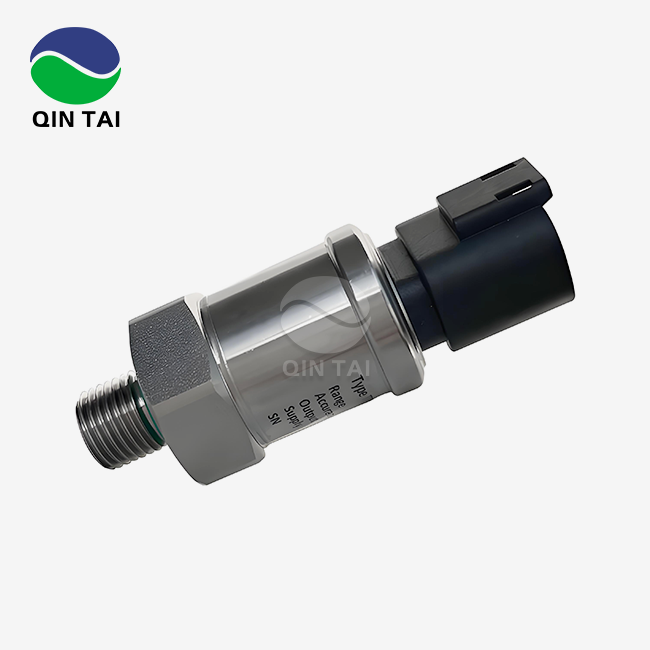
Partner With Qintai for Reliable Urea Dosing Pressure Sensor Solutions
Qintai Automotive Emission Technology Co., Ltd. Ltd has been China's top Urea dosing pressure sensor maker since 2001, providing key parts to major diesel engine makers like Weichai Power, Yuchai Power, and Quanchai Power. Our factories are ISO9001 and IATF16949 approved, and the sensors they make meet Euro VI and EPA emission standards. They also have 58 invention patents and strict testing methods to back them up.
We know how hard it is for buying managers to keep costs down while also making sure that parts are of good quality. Our engineering team is here to help you with all of your technical questions during the whole decision process. They can help you find the sensor specs that are best for your needs. We can make anything from prototypes to large amounts of standard sensors, and we can send them right away. If you need custom solutions for specialized equipment, we can also make those.
Qintai sensors are reliable and accurate, just what your aftertreatment systems need. They have a lot of approvals, such as CMC, Ex, UL, CE, REACH, and RoHS, which means they are accepted all over the world. Get in touch with our technical sales team at info@qt-sensor.com to talk about your sensor needs and find out how our 20 years of experience in emission control can help your supply chain. We welcome questions from OEM makers, system developers, and aftermarket sellers looking for a reliable urea dosing pressure sensor provider that wants to work with them for a long time.
References
1. Johnson, M., & Williams, R. (2022). Advanced Sensor Technologies for Diesel Emission Control Systems. Society of Automotive Engineers International.
2. Chen, H., Zhang, L., & Kumar, P. (2023). Precision Measurement in SCR Aftertreatment Applications. International Journal of Automotive Technology, 24(3), 487-502.
3. European Automobile Manufacturers Association. (2023). Technical Standards for Euro VI Emission Control Components. Brussels: ACEA Publications.
4. Roberts, D. (2021). Diesel Exhaust Fluid Systems: Design, Diagnosis, and Maintenance. Industrial Press Inc.
5. Schmidt, K., & Nakamura, T. (2023). Sensor Integration in Modern Emission Control Systems. International Council on Clean Transportation Technical Report Series.
6. Anderson, P., Liu, W., & Patel, S. (2022). Reliability Engineering for Automotive Sensors in Harsh Environments. Proceedings of the International Conference on Automotive Technologies, Detroit, Michigan.

Our customers’ satisfaction speaks for our quality — contact us to experience the same reliable service.