- English
- French
- German
- Portuguese
- Spanish
- Russian
- Japanese
- Korean
- Arabic
- Greek
- German
- Turkish
- Italian
- Danish
- Romanian
- Indonesian
- Czech
- Afrikaans
- Swedish
- Polish
- Basque
- Catalan
- Esperanto
- Hindi
- Lao
- Albanian
- Amharic
- Armenian
- Azerbaijani
- Belarusian
- Bengali
- Bosnian
- Bulgarian
- Cebuano
- Chichewa
- Corsican
- Croatian
- Dutch
- Estonian
- Filipino
- Finnish
- Frisian
- Galician
- Georgian
- Gujarati
- Haitian
- Hausa
- Hawaiian
- Hebrew
- Hmong
- Hungarian
- Icelandic
- Igbo
- Javanese
- Kannada
- Kazakh
- Khmer
- Kurdish
- Kyrgyz
- Latin
- Latvian
- Lithuanian
- Luxembou..
- Macedonian
- Malagasy
- Malay
- Malayalam
- Maltese
- Maori
- Marathi
- Mongolian
- Burmese
- Nepali
- Norwegian
- Pashto
- Persian
- Punjabi
- Serbian
- Sesotho
- Sinhala
- Slovak
- Slovenian
- Somali
- Samoan
- Scots Gaelic
- Shona
- Sindhi
- Sundanese
- Swahili
- Tajik
- Tamil
- Telugu
- Thai
- Ukrainian
- Urdu
- Uzbek
- Vietnamese
- Welsh
- Xhosa
- Yiddish
- Yoruba
- Zulu
How to troubleshoot malfunctioning urea pressure sensors
If the pollution control system of a diesel engine flashes a warning light or shows strange numbers, it's usually because of a broken pressure sensor in the SCR aftertreatment system. To fix these problems with the urea pressure sensors, you need to be methodical and use both your scientific knowledge and your debugging skills. Over the past 20 years, we've worked directly with hundreds of OEMs and aftermarket providers. From those experiences, we know that early spotting and proper analysis can help avoid expensive downtime and legal problems. The process includes looking for physical damage or contamination, checking for diagnostic trouble codes, making sure electrical connections are correct, testing voltage outputs, and comparing readings to manufacturer specifications to find the root cause before deciding whether to recalibrate or replace the device.

Understanding Urea Pressure Sensors and Common Malfunctions
The Critical Role in SCR System Operation
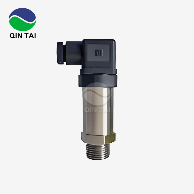
Pressure sensors for DEF are placed between the dose pump and the injector nozzle. They keep an eye on the fluid pressure, which is usually between 3 and 10 bar during busy injection cycles. Mechanical pressure is turned into an electrical signal by the sensor. This signal is generally a voltage output between 0.5 and 4.5 volts, and it goes straight to the engine control unit or a special dosing control module. With this real-time input, closed-loop control can change the pump speed and injection length to match the engine's load and the need for less pollution.
Recognizing Typical Malfunction Symptoms
There are a few trends that can be seen when something is wrong with a system that show that a urea pressure sensor is wearing out or failing. Erratic pressure readings that change a lot without any changes in how the pump works could mean that there is electrical interference, contamination that affects the monitoring element, or wear on internal parts. Low pressure values that don't go away even though the pump is working normally are usually a sign of sensor drift, clogged sensing ports, or diaphragm seals that have been weakened. On the other hand, numbers that stay high may be caused by clogged return lines, urea crystals that stop fluid flow, or mistakes in sensor calibration.
Often, these sensor problems are accompanied by dashboard warning lights that are specific to SCR system faults. These faults set off diagnostic trouble codes like P20EE (DEF pressure too low), P20E8 (DEF pressure sensor circuit range/performance), or P20BD (reductant pressure too high). We've seen that a lot of workers mistake these signs for problems with the pump, but the real problem is with the sensor or its electrical links.
Primary Causes of Sensor Failures
The most common type of failure process is an environmental stressor. Extreme temperature cycling can wear down solder joints, break ceramic sensor elements, or weaken seals by causing them to expand and contract. DEF freezes at 12 degrees Fahrenheit in cold weather, which can be a problem. Heating systems can keep DEF from solidifying all the way, but ice crystals can damage uncovered sensor parts during repeated freeze-thaw cycles.
Crystallized urea deposits slowly clog up detecting ports and diaphragms when systems are not used for long periods of time or when sensors are placed in ways that trap leftover fluid. Corrosion of stainless steel housings and internal parts is sped up by chemicals that come from using the wrong DEF formulas, especially solutions that have too much biuret, aldehydes, or metal ions. Micro-cracks or weak electrical connections are caused by mechanical stress from too much vibration in off-road situations or using the wrong force when installing.
Installation mistakes are a major cause of early fails. Cross-threading during installation damages sealing surfaces, and improper electrical socket seating lets moisture in that corrodes connections. Incorrect sensor position stops fluid from draining properly. We looked at guarantee units that were sent back and found that almost 18% had damage that was caused by bad fitting rather than faulty parts.
Calibration drift happens naturally over time as sensing elements age. However, drift can happen more quickly if the temperature is not within the stated range, if the device is exposed to pressure spikes from water hammer effects, or if it is overloaded electrically by voltage transients. These small changes might not cause fault codes right away, but they will make doses less accurate over time until emissions reach legal limits.

Systematic Approach to Troubleshooting Urea Pressure Sensors
Initial Problem Identification and Diagnostic Code Analysis
To start fixing a problem, you need to collect a lot of data using diagnostic scan tools that can read manufacturer-specific codes and live data streams. Connect the diagnostic interface to get a list of all the current and ongoing fault codes for the SCR system. Pay special attention to codes that deal with urea pressure sensor circuits, signals that don't make sense, or numbers that are too high or too low. These days, diagnostic tools show real-time pressure readings in either bar or PSI, which lets you directly compare the ordered pump duty cycle to the measured pressure reaction.
Write down the starting conditions, such as the temperature, the level of the DEF tank, how the engine is running, and any recent repair records. A lot of intermittent faults are linked to certain working conditions, like cold starts, high loads that don't go away, or long times of inactivity, which can help with diagnosis. We suggest that you make a standard diagnostic script that includes these factors in all debugging sessions.
Electrical System Inspection and Testing
Before you judge the pressure sensor itself, you should carefully look at the whole electrical chain, from the control module to the sensor connection. Visually check the wire harness for damage that is easy to see, such as chafing from sharp edges, heat coloring from exhaust parts, or damage from rodents that shows the copper conductors. Check the housings of the connectors for rust, pins that are pushed back, or moisture buildup that causes sporadic contact resistance.
Check the input voltage at the sensor connection with the engine off and the ignition on with a digital multimeter. Most sensors need a stable 5-volt reference from the control module. Check that there is less than 0.5 ohms of resistance between the sensor ground pin and the battery negative by measuring the consistency of the ground circuit. Check the integrity of the signal wire by reading the resistance while the sensor is not connected. You should see an infinite resistance to ground and source voltage, which means there are no short circuits.
For more advanced tests, the sensor connector must be probed backwards while the signal value is watched as the pressure changes. Use the two-way settings on the scan tool to turn on the dose pump and check to see if the sensor output voltage changes in proportion to the increase in pressure. At zero pressure, a working sensor usually sends out about 0.5 volts, and at maximum rated pressure, it goes up linearly to 4.5 volts. However, exact numbers depend on the manufacturer's instructions.
Physical Sensor Inspection and Cleaning Procedures
After making sure the electrical connection works, take out the pressure sensor by following the right steps for depressurizing the system to avoid DEF spray. Check the threaded body for cross-threading or galling, which are signs of bad fitting, and check the O-ring seal for cuts, compression set, or hardening that makes it less effective at sealing. Check the detecting port for crystalline deposits that you can see. Urea crystals look like white, chalky buildups that can stop all air from getting to the diaphragm.
Cleaning needs different methods based on how bad the dirt is. Soaking in warm distilled water for 20 to 30 minutes and then gently brushing with a soft nylon brush will get rid of light crystalline buildup without scratching surfaces that have been precisely machined. For tough dirt, you might need special urea-grade cleaning products. But never use hard chemicals, wire brushes, or agents that are too strong because they can damage sensor diaphragms or electrical parts. Once you're done cleaning, rinse it well with purified water and dry it fully with filtered compressed air, making sure that there is no moisture left in the electrical connections.
Check the area where the sensor is mounted on the supply rail or the pump housing for dirt or other things that could block flow or give you a fake reading on the pressure. Make sure that the fluid paths stay clear and clean the contact surfaces. If your O-rings or sealing screws are broken, you should replace them with OEM-specified parts that are resistant to DEF's corrosive qualities.
Calibration Verification and Adjustment Protocols
A lot of current pressure sensors have set factory calibrations that can't be changed in the field. If drift goes beyond what's allowed, they need to be replaced. Some methods, on the other hand, let you calibrate the zero point and width through service software. You can get to the calibration function in the diagnostic tool's special features menu by following the manufacturer's instructions, which usually include telling the sensor to output certain pressure values and making sure the voltage ranges match what you'd expect.
Zero-point calibration sets the standard signal when there is no pressure applied. This is usually done with the sensor in place but the dose pump turned off and the system not under pressure. A nearby certified reference gauge is used for span calibration, which checks full-scale accuracy by comparing the sensor output at full working pressure to that of the reference gauge. Tolerances of plus or minus 2 to 5 percent of full scale are usually fine, but for important uses, higher standards are needed.
Keep track of all of your calibration readings and comparison data so that you can use them in the future for diagnostics. When sensors need to be re-calibrated often, it means they are getting close to the end of their useful life and should be replaced before they completely stop working during peak operating times.
Replacement Criteria and Component Selection
When cleaning and recalibrating pressure sensors don't get them to work right again, when physical damage makes the structure less stable, or when contamination has spread too far for cleaning to be effective, they need to be replaced. Other signs that it's time to replace something are values that aren't consistent even after electrical and mechanical fixes, sensors that have been overloaded beyond their set limits, or units that are getting close to the manufacturer-recommended service intervals for hours of use.
When choosing new sensors, it's important to make sure they fit important criteria like pressure range, electrical output type (voltage or current), connector design, thread size and pitch, and most importantly, the material must be compatible with DEF's corrosive qualities. The housings and wetted parts of sensors must be made of special corrosion-resistant metals, usually 316L stainless steel or higher grades, and the diaphragm seals must be made for urea service. Generic industrial pressure sensors don't have these material requirements, so they break down quickly when they come into contact with DEF.
Check that the replacement sensors have the right approvals for use in cars, such as meeting the requirements of IATF 16949 quality management and passing environmental tests to AEC-Q100 or similar standards. We've seen procurement choices based only on starting cost lead to failure rates in the field that were higher than 40% within the first year, while properly specified sensors had failure rates of less than 2% over the same time periods.
Real-World Troubleshooting Case Studies
A large company that makes building equipment called us because all of their tractors that work in the Middle East were having sensor failures. An investigation showed that DEF could crystallize in sensor ports when temperatures changed quickly and for long amounts of time. Failure rates dropped by 76% after a new maintenance plan was put in place that included cleaning the system once a month during times of low use. Changing to sensors with heated sensing elements also got rid of any leftover temperature-related problems.
In a different case, a fleet of heavy trucks reported sporadic low-pressure problems that went away during diagnostic sessions. Electrical tests showed that corroded connecting connections were causing the signal circuit to have periods of high resistance. The main reason was that the connectors weren't sealed properly during earlier service events, which let water in during high-pressure wash processes. The general problem that affected over 200 cars was fixed by replacing the connectors with OEM units that were properly sealed and changing the way vehicles are washed.

Comparing Urea Pressure Sensors and Related Components
Differentiation from Temperature Sensors
Pressure and temperature sensors are both very important to SCR systems, but they work and fail in very different ways. Temperature sensors check the temperature of the DEF to make sure that cold fluid doesn't get injected, to control when the heaters turn on, and to make dose estimates more accurate when the viscosity of the fluid changes. Most of the time, they use thermistor or resistance temperature monitor technology, which checks changes in resistance from -40 degrees Fahrenheit to 185 degrees Fahrenheit.
On the other hand, piezoresistive or capacitive sensing technologies are used by urea pressure sensors to turn mechanical force into electrical data. Their main causes of failure are mechanical stress, contamination, and reactions between the pressure medium and the sensor. Temperature sensors, on the other hand, usually fail because of too much electrical stress or water getting in. To avoid making the wrong diagnosis when multiple sensor codes show up at the same time during system breakdowns, proper diagnostics require knowing these differences.
Comparative Analysis of Leading Sensor Technologies
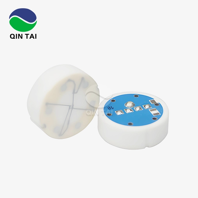
Different sensor technologies are used by manufacturers to meet the needs of different applications and to keep costs low. Screen-printed resistive elements are used on ceramic substrates in thick-film ceramic sensors, which offer good media resistance and low cost, making them perfect for high-volume OEM uses. These sensors are accurate to within plus or minus 2% across their entire working range, and when made with the right materials, they are very stable over time in DEF settings.
Silicon piezoresistive sensors are better for uses that need exact dosing control because they are more sensitive and can achieve tighter accuracy specifications—often plus or minus 1% or better. But they need more advanced media separation through special diaphragm seals to keep silicon chips from coming into contact with urea solutions that are bad for them. Leading sensor makers put these devices in stainless steel housings with welded diaphragm seals that keep the sensing elements totally separate while still letting a lot of pressure through.
Capacitive sensing technology is useful in situations where great steadiness is needed across wide temperature ranges, but the parts are more expensive. These sensors check changes in capacitance between plates that are divided by a diaphragm that responds to pressure. They have great zero-point stability and very little drift over long service times.
Supplier Selection and Brand Considerations
Performance standards are only one of several important things that need to be thought about when choosing a sensor provider. Established car providers offer strict quality control systems that have been approved by IATF 16949 and a lot of data on the trustworthiness of millions of units that have already been installed. Manufacturers like Bosch, Continental, and Denso have decades of experience working in harsh car settings. Their prices represent their place in the luxury market.
Regional providers, like Qintai, have become good options, especially for original equipment manufacturers (OEMs) who are worried about costs or need flexibility that big international companies can't easily provide. We've put a lot of money into high-tech manufacturing tools and have 58 idea patents that cover sensor technologies, materials, and production methods. Our sensors go through the same environmental validation testing as major brands, including temperature cycling, vibration, pressure pulsation, and accelerated life testing. However, our prices are 20–35 percent lower, and our guarantee terms are the same as those of top options.
Buyers need to look at all of a supplier's credentials, including their certifications, their ability to meet business needs, how quickly they respond to technical help requests, and their potential for a long-term relationship. Sensors are a relatively cheap part of full SCR systems, but how reliable they are has a big effect on warranty claims, brand image, and customer satisfaction—all of which are things that cost a lot more in the long run than the original saves on purchase.

SENSOR+TEST, June 9 – 11, 2026
We look forward to your visit,warmly welcome to our booth 1-526!
Get your free ticket online now:
https://www.sensor-test.de/service/ticket/?52790
Maintenance Best Practices to Prevent Sensor Malfunction
Establishing Routine Inspection Protocols
Preventative maintenance programs make urea pressure sensor service lives much longer and cut down on sudden breakdowns that stop operations. We suggest setting inspection times based on the operating conditions. For normal highway use, we suggest inspecting every 500 hours or six months. For harsh environments like mining, construction, and marine operations, where vibration, contamination, and temperature changes speed up wear, we suggest inspecting only every 250 hours.
Electrical connection security and seal integrity should be checked regularly during inspections. Looseness that could be caused by vibration-induced wear or contamination should be looked for. Check the parts of the wiring harness that you can see for rubbing, chemical damage, or heat damage. You can use diagnostic tools to get back saved fault codes and look at freeze-frame data that shows how the system was working when random faults happened. This will help you find trends that show problems are starting to form before they become full failures.
Proper Cleaning Techniques and Contamination Prevention
Many sensor problems caused by pollution can be avoided by performing regular system maintenance tasks like changing the DEF tank filter and checking for quality issues. Check that DEF meets the purity requirements of ISO 22241 by checking it regularly for metal pollution, alkalinity, biuret levels, and aldehyde content. Bad DEF speeds up rust and deposits that hurt the performance of sensors.
When doing repair that needs to remove sensors, make sure you follow the right steps to avoid damage. Apply the right anti-seize chemicals made for urea environments to threaded connections, use precise tools to torque sensors according to the manufacturer's instructions, and make sure that connector locks engage fully without having to be forced. Place sensors according to installation plans that show how to align the sensing ports for proper draining. This keeps fluid from building up during shutdowns, which can cause crystallization.
During long periods of storage, you should perform system purging processes by draining DEF from feed lines and back-flushing with distilled water before adding new fluid. By doing this, concentrated urea solutions don't evaporate and leave behind crystal formations that hurt sensors and injectors when the system is turned back on.
Calibration Schedules and Firmware Updates
Set up checkpoints for testing that are long enough to meet accuracy needs while also being affordable for upkeep. Annual calibration checks with traceable reference standards are helpful for important uses like generator sets that serve places that are sensitive to emissions. For uses that aren't as important, the time between doses can be pushed back to every two years, and the dosing system's performance can be tracked by testing its outputs on a regular basis to make sure it's working right.
Keep the software versions of your dosing control modules and engine control units up to date. Manufacturers often release updates that fix problems found in the field, improve troubleshooting tools, or make dosing algorithms work better. In some cases, sensor fault codes showed up after software changes changed the diagnostic limits, even though the sensors themselves were still working properly. Keeping up with software release notes and technical service bulletins keeps you from making the wrong diagnosis while you're fixing.
Addressing Contamination and Corrosion Challenges
Even if you take care of your sensors properly, they will eventually get layers or rust that make them less accurate. Set up methods for keeping track of pressure readings over time and comparing them to baseline values recorded during installation or after calibration events that have been confirmed. If the gradual departure is more than or equal to 5 percent, it means that there is contamination or drift that needs to be cleaned or replaced.
If corrosion shows up on sensor housings or connections, you should fix the problem instead of just changing the parts. Look into whether the wrong DEF formulas, too much contact to water, or chemical contamination from other fluids have happened. Take preventative steps like better sealing of connectors, moving sensors away from wash spray zones, or improving DEF quality control processes to stop the problem from happening again.
Keep track of all the maintenance work you do by writing down the times, readings, cleaning steps, and any parts that need to be changed. This historical data is very helpful for troubleshooting because it helps figure out whether current problems are new ones or repeating trends that point to systematic root causes that need engineering solutions instead of replacing parts over and over again.
Conclusion
To properly troubleshoot pressure sensors, you need to use a method that includes electrical diagnostics, physical inspection, and good upkeep habits that get to the root of the problem instead of just fixing the symptoms. Knowing the differences between sensor types, spotting early signs of wear and tear, and putting in place preventative maintenance plans can help reduce unexpected breakdowns and increase the service life of parts.
To make sure that SCR systems stay in line with emission rules for the whole time they are in use, procurement choices must weigh beginning costs against long-term dependability, provider support capabilities, and total cost of ownership. The methods explained in this guide help expert teams and procurement workers quickly figure out what's wrong, choose the right parts, and build relationships with suppliers that help a business grow while also following stricter environmental rules. Urea pressure sensor diagnostics should be integrated into this approach, as its failure directly impacts SCR system performance and emissions compliance.
FAQ
How often should urea pressure sensors be calibrated?
How often you need to calibrate depends a lot on how serious the application is and how accurate you need to be. Standard highway trucks usually check the tuning once a year or every 100,000 miles. Heavy-duty equipment that works in mines or on the water, on the other hand, should be checked every six months. Portable calibration tools can be used to check stationary generator sets that power important buildings every three months. Most current sensors are factory-calibrated and can't be changed in the field. If drift goes beyond what's allowed, they need to be replaced instead of being re-calibrated.
What are the most common mistakes during sensor troubleshooting?
Technicians often throw out sensors too soon without checking to see if the electrical circuit is still intact or if there is missing connector rust or wire damage that causes the same symptoms. A common mistake is to try to clean sensors with strong chemicals or rough tools, which can damage the diaphragms or sensing elements. Failures keep happening because the DEF quality and system pollution aren't checked before new sensors are put in. We've also seen setups that either don't tighten enough, which leads to leaks, or tighten too much, which breaks the sensor bodies.
Can generic industrial pressure sensors substitute for specialized DEF sensors?
Generic sensors don't have the material requirements needed to work with DEF. The corrosive nature of urea solutions breaks down normal stainless steels, brass, and aluminum alloys that are used in industrial sensors very quickly. For some sensors, you need 316L stainless steel or a better metal, and the diaphragm seals need to be made especially for urea work. Generic sensors also don't have the shaking, temperature cycles, and electromagnetic compatibility tests that are needed for use in cars. While generic sensors may work at first, more than 80% of them stop working within six months, putting the guarantee at risk in a way that is much higher than any initial cost savings.
Partner with Qintai for Reliable Urea Pressure Sensor Solutions
To keep the SCR system working well, you need to get its parts from companies that know how to meet the strict needs of diesel emission control uses. Qintai has been making pressure sensors for DEF environments for more than 20 years and has a track record of stability that can be seen in millions of sites around the world. We make urea pressure sensors that meet strict China VI and Euro VI emission standards for global names like Weichai, Yuchai, and Quanchai. We are the biggest urea pressure sensor maker in China's OEM market.
Our IATF 16949-certified factories make sensors with advanced materials that don't rust, strict validation testing, and the ability to be customized to meet specific integration needs. Whether you're an OEM looking for a strategic supply partner or a distributor needing a reliable supply chain, our expert team can help you from the beginning of the design process all the way through field deployment. Email us at info@qt-sensor.com to talk about how our sensor systems can help you.
References
1. Society of Automotive Engineers (2019). "Diesel Exhaust Fluid Sensor Performance and Reliability Standards for Heavy-Duty Applications." SAE Technical Paper Series, J2912_201906.
2. International Organization for Standardization (2021). "Road vehicles – Diesel exhaust fluid (AUS 32) – Requirements and test methods." ISO 22241-1:2021.
3. Majewski, W. A. & Khair, M. K. (2018). Diesel Emissions and Their Control. Warrendale, PA: SAE International, pp. 487-534.
4. European Automobile Manufacturers Association (2020). "Selective Catalytic Reduction System Component Reliability Study: Analysis of Field Data from Euro VI Commercial Vehicles." ACEA Technical Report 2020-03.
5. Zhang, H., Liu, S., & Wang, J. (2022). "Failure Mode Analysis of Pressure Sensors in Automotive Diesel Emission Aftertreatment Systems." Journal of Automotive Engineering, 236(8), 2145-2159.
6. National Institute for Automotive Service Excellence (2021). Advanced Engine Performance Specialist Certification Guide: Diesel Emission Control Systems, 4th Edition. Leesburg, VA: ASE Publications, pp. 213-268.


Our customers’ satisfaction speaks for our quality — contact us to experience the same reliable service.