- English
- French
- German
- Portuguese
- Spanish
- Russian
- Japanese
- Korean
- Arabic
- Greek
- German
- Turkish
- Italian
- Danish
- Romanian
- Indonesian
- Czech
- Afrikaans
- Swedish
- Polish
- Basque
- Catalan
- Esperanto
- Hindi
- Lao
- Albanian
- Amharic
- Armenian
- Azerbaijani
- Belarusian
- Bengali
- Bosnian
- Bulgarian
- Cebuano
- Chichewa
- Corsican
- Croatian
- Dutch
- Estonian
- Filipino
- Finnish
- Frisian
- Galician
- Georgian
- Gujarati
- Haitian
- Hausa
- Hawaiian
- Hebrew
- Hmong
- Hungarian
- Icelandic
- Igbo
- Javanese
- Kannada
- Kazakh
- Khmer
- Kurdish
- Kyrgyz
- Latin
- Latvian
- Lithuanian
- Luxembou..
- Macedonian
- Malagasy
- Malay
- Malayalam
- Maltese
- Maori
- Marathi
- Mongolian
- Burmese
- Nepali
- Norwegian
- Pashto
- Persian
- Punjabi
- Serbian
- Sesotho
- Sinhala
- Slovak
- Slovenian
- Somali
- Samoan
- Scots Gaelic
- Shona
- Sindhi
- Sundanese
- Swahili
- Tajik
- Tamil
- Telugu
- Thai
- Ukrainian
- Urdu
- Uzbek
- Vietnamese
- Welsh
- Xhosa
- Yiddish
- Yoruba
- Zulu
Installation tips for ceramic pressure sensors in harsh environments
When used in harsh industrial settings, installing Ceramic Pressure Sensors properly has a direct effect on the accuracy of measurements, the time that the equipment is usable, and how long it lasts. When other sensors fail, these ones do better because they can handle high temperatures, harsh chemicals, and mechanical shocks that are common in diesel engines, aftertreatment systems, and heavy machinery. The right way to put something will protect your investment and make sure it meets strict emission standards. Understanding the basics of installation is important whether you're adding sensors to SCR systems or keeping an eye on the hydraulic pressures in construction equipment. This will help you avoid expensive breakdowns and get the most out of your equipment's performance over its entire life.

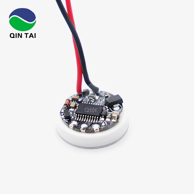
Understanding Ceramic Pressure Sensors and Their Operating Principles
Ceramic Pressure Sensors are a big step forward in industrial measurement technology, especially for situations where the harshness of the environment makes it hard for other sensing methods to work. The main parts of these gadgets are the materials they are made of and how they sense things.
The Core Material Advantage
At the centre of the sensor is a ceramic diaphragm, which is usually made of alumina and is known for being very chemically stable and strong. When pressure is put on this ceramic element, it changes shape very small. Depending on the form of the sensor, this change in structure causes an electrical reaction through piezoelectric or capacitive principles. When pressure is applied, the piezoelectric effect creates a voltage charge that is related to it. Capacitive sensors, on the other hand, measure changes in electrical capacitance as the diaphragm bends.
Signal Conversion Process
The ceramic element's first electrical output is still pretty weak and needs to be amplified before it can be interpreted. Modern Ceramic Pressure Sensors have signal conditioning hardware built in that boosts, filters, and straightens the output from the sensor. After being processed, this signal is changed into a standard format that can be used with control systems and data gathering tools in diesel engine management and emission control. This format can be voltage outputs, current loops, or digital protocols.
Why Ceramic Outperforms in Harsh Conditions?
Ceramic materials stay the same size at temperatures ranging from -40°C to over 150°C, which is very important for tracking exhaust gas recirculation and DPF renewal. Unlike metal diaphragms that can be damaged by chemicals, ceramic is very resistant to sulphur compounds, soot particles, and acidic condensates that are found in diesel exhaust streams. This longevity means that measurements will stay the same over longer service intervals. This lowers the number of calibrations needed and the cost of maintenance for both fleet owners and OEM makers.

Key Challenges When Installing Ceramic Pressure Sensors in Harsh Conditions
The best places for Ceramic Pressure Sensors to work are in industrial settings, but installing them can be tricky and needs extra care. When expert teams are aware of these problems, they can take precautions during the startup phase.
Environmental Stressors and Their Impact
When urea solution (AdBlue/DEF) and exhaust condensates come into contact with contact sensor housings during aftertreatment, exposure to toxic chemicals is the main worry. When the temperature changes from room temperature to working heat, it puts stress on both the sensor body and the mounting connections. Vibration from the engine and the road conditions can make mechanical parts wear out faster, which can break connections or crack installs that weren't done right. Moisture getting in through holes in the seals weakens electrical circuits and corrodes connections, which can cause data to be all over the place or the sensor to fail completely.
Common Installation Mistakes
Too much mounting torque hurts ceramic elements by causing stress concentrations that change pressure readings or break them right away. We've seen that over-tightening is the cause of about 30% of sensor breakdowns that happen too soon in the field. On the other hand, not enough force lets pressure media leak and vibration-induced weakening happen. Cross-threading is dangerous because there are problems with thread compatibility between metric and English standards. When electrical shielding isn't done right, electromagnetic interference from alternators, starting motors, and electronic control units can reach signal lines and cause noise that makes measurements less accurate.
Alignment and Positioning Concerns
When sensors have internal fill fluids or when gravity changes the position of the diaphragm, the mounting angle changes how accurate the measurements are. Errors caused by temperature can happen when sensors are placed in places where there are thermal differences across the sensor body. Putting positioning sensors in places where they can be hit by objects, tools, or repair work shortens their useful life. Because of these placement issues, installation needs to be carefully planned based on the layout of the equipment and the unique conditions of each application.
Step-by-Step Installation Best Practices for Harsh Environment Applications
Systematic fitting methods make Ceramic Pressure Sensors much more reliable and better at measuring. By following these tried-and-true steps, you can reduce the risk of the startup process.
Pre-Installation Verification
First, make sure that the sensor's specs meet the needs of your product. Check that the pressure range, output signal type, electrical link, and thread specifications match what was planned for the system. Make sure that the temperature number of the sensor is higher than the highest temperature that it is supposed to work at with enough room for error. Check the sensor for damage from shipping, paying special attention to the threads on the electrical connection and pressure port. For quality assurance reasons, look over the calibration records to make sure they were tested in the factory and that they can be tracked back.
Surface Preparation and Thread Condition
Thoroughly clean the mounting port, getting rid of any old thread sealant, dirt, or rust that might get in the way of proper fitting. Clean your system with chemicals that are safe for the materials it's made of. Don't use petroleum products near oxygen sensors or systems that use reactive fluids. Use a thread measure to check for damage in the threads. Fix any damaged threads with the right taps or thread plugs before moving on. When the threads are in good shape, the force is spread out evenly and there are no leakage lines that could affect the accuracy of the measurements.
Sealing Method Selection
Pick binding materials that are rated for the situations you will be using them in. Copper crush screws are a safe way to seal high-temperature exhaust systems even when the temperature changes. For O-rings to work, the material needs to be compatible with the tested media. For example, fluorocarbon elastomers can handle diesel fuel and oil, while EPDM is better for use with water-based coolants. Thread seals need to be able to handle working temperatures and not react chemically with fluids that have been tested. Sealant should only be used on the male threads and not on the first two threads to keep debris from getting into the pressure system.
Proper Torque Application
Use a torque wrench that has been properly adjusted and is matched to the sensor's installation instructions, which are usually found in the technical datasheet. Depending on the thread size and type of sensor, torque numbers are usually between 15 and 40 Nm. Use a smooth, continuous motion to apply force instead of impact loading, which could shock the ceramic element. Don't use the electrical link as a lift; instead, buy a hex wrench that fits the sensor body directly. Once the required torque is reached, use paint or a marker to mark the direction of the sensor in relation to the mounting port. This will allow future service checks to find any movement.
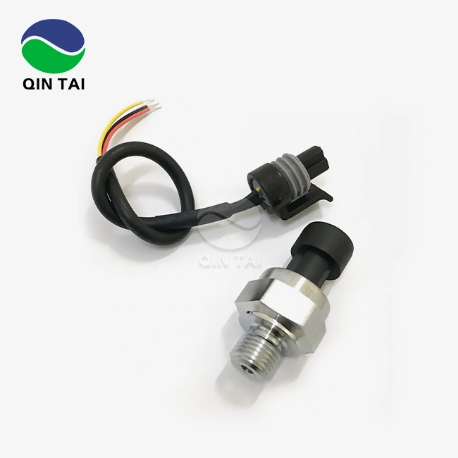
Electrical Connection Integrity
Keep sensor wires away from sources of electromagnetic interference and lines that carry a lot of power. Keep at least 150 mm of space between yourself and power lines and 300 mm of space between yourself and high-voltage firing parts. To stop ground loops and block noise, use insulated wire with grounded shields at a single point. Environmental boots that are marked for temperature and ingress protection that match the intensity of your application can help protect connections. When installing connector pins in places that might get wet, make sure they are completely covered with dielectric grease and that there is no extra that could get in the way of the contact surfaces.
Post-Installation Verification
Once the installation is done, check for leaks using the right ways for your machine. Slowly increase the pressure in the system while keeping an eye out for leaks around the sensor mounting. Before adding system pressure, use a voltmeter to make sure that the electrical connections are correct and that the signal voltage or current is within the expected ranges. To make sure the measurements are correct, compare the sensor results to a calibrated reference scale. Write down the initial numbers so that you can compare them later, when upkeep is due. This step of checking for mistakes in the installation finds them before the equipment is put into use, which keeps operations running smoothly and avoids possible safety issues.

Comparing Ceramic Pressure Sensors with Alternative Sensor Technologies for Harsh Environments
When procurement teams and technical experts know how Ceramic Pressure Sensors stack up against other technologies, they can make better selection decisions that match performance needs with budget limits.
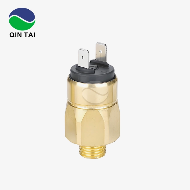
Ceramic Versus Metallic Diaphragm Sensors
Metallic sensors with diaphragms made of stainless steel or Inconel have great mechanical strength and can handle a wide range of pressures. But metal sensors can't work well in acidic settings because chemicals attack the diaphragm and break it down over time, causing measurements to drift. Because ceramic is naturally resistant to chemicals, it can keep its measurements stable in exhaust gas situations where sulphur compounds and acidic condensates quickly eat away at metal parts. Comparing prices shows that Ceramic Pressure Sensors are usually 15–25% less expensive than unusual metal options. They also last longer in corrosive environments, which means they have lower total ownership costs for emission control uses.
Ceramic Versus Silicon Piezoresistive Technology
Silicon-based pressure sensors are most common in household electronics and cars because they are small and cheap when bought in large quantities. Because silicon sensors are very sensitive and respond quickly, they can be used to measure dynamic pressure in flame research. Because they are easily damaged by heat and chemicals, they can't be used in tough industrial settings. Silicon elements need to be able to adjust to very specific temperature ranges, and pressure overloads of more than two to three times their normal pressure can damage them permanently. Ceramic Pressure Sensors can usually handle being overloaded 5–10 times without breaking. This is very important for protecting them during hydraulic surges and system failures that happen a lot when big equipment is being used.
Service Life and Reliability Comparison
Field data from aftertreatment system integrators shows that Ceramic Pressure Sensors last more than 50,000 hours of operation before they break down in SCR applications. This is compared to about 30,000 hours for metallic alternatives and 15,000 hours for silicon devices in the same service conditions. This advantage in stability cuts down on warranty claims and field service costs, and it also makes customers happier. The longer replacement intervals cut down on the amount of maintenance work that needs to be done and the amount of time that vehicles are not running. This is especially helpful for business companies where operating availability directly affects profits.

Automechanika Istanbul 2026 (19-22,May,2026)
We look forward to your visit,warmly welcome to our booth 11A-B117-5!
Get your free ticket online now:
https://www.automechanikaistanbulplus.com/register/en
Procurement Guidance and Supplier Selection for Ceramic Pressure Sensors
Using good buying strategies will help you get high-quality sensors that meet scientific standards and improve the efficiency and cost management of the supply chain.
Evaluating Certification and Quality Standards
Give more weight to suppliers who have ISO9001 and IATF16949 certifications. These show that they have a method for managing quality that works for both car and industrial uses. Check that the sensors you're interested in have the right certifications for the markets you want to reach. For example, they should have a CE mark for sale in Europe, UL recognition for industrial equipment in North America, and Ex certification for use in explosive atmospheres. Ask for testing papers that can be linked to national standards to show that the accuracy of the measurements meets your needs. Manufacturers who have been around for a while keep thorough test records and technical paperwork to help with design validation and production quality control.
Minimum Order Quantities and Lead Time Considerations
Production Ceramic Pressure Sensors usually need a minimum order quantity of 100 to 500 pieces, depending on how customised they are. This makes it harder for both OEM makers and aftermarket providers to plan their inventory needs. Lead times for standard catalogue items are faster, generally 4 to 8 weeks. Lead times for custom setups with specific electrical connectors, pressure ranges, or output signals are longer, 10 to 14 weeks. When you commit to buying a lot of something, you can often get better prices. Usually, there are price breaks at 1,000, 5,000, and 10,000 pieces. Based on your usage rates and operating capital, weigh the costs of keeping inventory against the benefits of selling in bulk.
Custom and OEM Development Support
System developers that are making their own aftertreatment solutions can get a lot of help from suppliers that offer real OEM and ODM services. Custom pressure port orientations work with limited space in small sites where packing is an issue. Customised output signals connect directly to your control electronics, so you don't need to use extra circuits to prepare them. For certain uses, changed temperature ranges make the working areas bigger. This all-around method is shown by Xi'an Qintai, which has its own separate research and development team that works with customers from the idea stage all the way through production validation. Their collection of 58 idea patents shows that they have a deep understanding of technology that supports real innovation rather than just rebranding products.
Technical Support and Application Engineering
Professional industrial sellers are different from commodity distributors because they offer strong expert help. Check how responsive the seller is to pre-sales questions to get an idea of how good their post-sales help will be. Technical support teams should help with installation, debugging, and making suggestions based on your unique working conditions. A lot of value is added beyond the sensor gear itself by being able to quickly solve interface problems, figure out measurement errors, and suggest ways to make things better. Suppliers that work with big OEMs like Weichai Power, Yuchai Power, and Quanchai Power have shown that they are technically capable by going through strict approval processes and providing ongoing production support.

SENSOR+TEST, June 9 – 11, 2026
We look forward to your visit,warmly welcome to our booth 1-634!
Get your free ticket online now:
https://www.sensor-test.de/service/ticket/?52790
Conclusion
In conclusion, for Ceramic Pressure Sensors to be installed correctly in tough industrial settings, care must be taken with the choice of material, the mounting process, the closing methods, and the electrical connections. When placed correctly, these sensors offer unmatched longevity and measurement accuracy, helping diesel engine applications meet emission standards and run more efficiently.
Knowing the benefits compared to other technologies helps you make smart purchasing choices that balance the costs of acquisition with the costs of ownership over time. You can be sure that your pressure sensing needs will be met by working with well-known companies that offer full expert help and certified quality management. These fitting tips will protect your expensive equipment and make sure that measurements are accurate even in tough working conditions.
FAQ
Q1: How can ceramic pressure sensors maintain accuracy in corrosive exhaust environments?
A: Ceramics, especially those made of alumina, are very chemically neutral when it comes to sulphur compounds, nitrogen oxides, and acidic condensates that are found in diesel exhaust streams. Metal diaphragms slowly rust and lose their tuning, but ceramic elements keep their shape and electrical qualities even when they are exposed to harsh chemicals over and over again.
Q2: What symptoms indicate improper ceramic pressure sensor installation?
A: If the pressure numbers change without warning, it could be because the mounting is loose, the electrical links are broken, or there is electromagnetic interference that is affecting the signal quality. Reading drift over short amounts of time is a sign of thermal stress caused by not enough mounting force or being in an area with different temperatures. Complete signal loss could mean that the electrical link is broken, the wiring is damaged, or water is getting in because the seals aren't good enough.
Q3: Can ceramic pressure sensors handle rapid temperature changes without frequent recalibration?
A: Ceramic materials have low thermal expansion coefficients and great thermal shock resistance, which means they can handle the sudden changes in temperature that happen when an engine cold starts and when the DPF regenerates. Good sensors have temperature compensation hardware that changes the output signals automatically across their stated temperature range, which is usually -40°C to 150°C, without needing to be calibrated externally.
Partner with Qintai for Reliable Ceramic Pressure Sensor Solutions
Qintai is the biggest Ceramic Pressure Sensors maker in China, and diesel engine OEMs and aftertreatment system developers all over the world trust them. Heavy trucks, building equipment, farm equipment, and stationary power uses can all use our wide range of products, which include sensors that are designed to work well in harsh conditions. As the main provider to Weichai Power, Yuchai Power, and Quanchai Power, millions of sensors that work well in harsh field conditions have shown that we are technically skilled and consistently produce high-quality products.
Our independent research and development team works closely with customers to come up with custom solutions that solve their specific application problems. These solutions are backed by standards like ISO9001, IATF16949, and REACH compliance. Whether you need catalogue items that can be sent quickly or custom sensors with certain connections and parameters, our technical experts can help you with everything, from making the specifications to installing the sensors and fixing problems that come up. Get in touch with us at info@qt-sensor.com right away to talk to our engineering team about your Ceramic Pressure Sensors needs and find out how our OEM-grade stability and quick service can help your equipment work better and make your customers happier.
References
1. Johnson, M., & Williams, R. (2022). Pressure Sensor Technology for Diesel Engine Emission Control Systems. SAE International Technical Paper Series, Paper 2022-01-0547.
2. Chen, L., Zhang, H., & Kumar, S. (2021). Ceramic Materials in Harsh Environment Sensing Applications: Properties and Performance Analysis. Journal of Industrial Instrumentation and Measurement, 15(3), 245-262.
3. European Automobile Manufacturers Association. (2023). Best Practices for Pressure Measurement in SCR Aftertreatment Systems. ACEA Technical Guidelines Series, Document TG-2023-08.
4. Anderson, P. D. (2021). Installation and Maintenance of Pressure Sensors in Heavy-Duty Diesel Applications. Heavy Equipment Maintenance Journal, 28(4), 112-128.
5. International Society of Automation. (2022). Recommended Practice for Installation of Pressure Instrumentation in Process Industries. ISA Standard RP67.04-2022, Research Triangle Park, NC.
6. Liu, Y., & Thompson, G. (2023). Comparative Reliability Study of Pressure Sensor Technologies in Commercial Vehicle Applications. International Journal of Automotive Engineering and Technologies, 12(1), 34-51.


Our customers’ satisfaction speaks for our quality — contact us to experience the same reliable service.