- English
- French
- German
- Portuguese
- Spanish
- Russian
- Japanese
- Korean
- Arabic
- Greek
- German
- Turkish
- Italian
- Danish
- Romanian
- Indonesian
- Czech
- Afrikaans
- Swedish
- Polish
- Basque
- Catalan
- Esperanto
- Hindi
- Lao
- Albanian
- Amharic
- Armenian
- Azerbaijani
- Belarusian
- Bengali
- Bosnian
- Bulgarian
- Cebuano
- Chichewa
- Corsican
- Croatian
- Dutch
- Estonian
- Filipino
- Finnish
- Frisian
- Galician
- Georgian
- Gujarati
- Haitian
- Hausa
- Hawaiian
- Hebrew
- Hmong
- Hungarian
- Icelandic
- Igbo
- Javanese
- Kannada
- Kazakh
- Khmer
- Kurdish
- Kyrgyz
- Latin
- Latvian
- Lithuanian
- Luxembou..
- Macedonian
- Malagasy
- Malay
- Malayalam
- Maltese
- Maori
- Marathi
- Mongolian
- Burmese
- Nepali
- Norwegian
- Pashto
- Persian
- Punjabi
- Serbian
- Sesotho
- Sinhala
- Slovak
- Slovenian
- Somali
- Samoan
- Scots Gaelic
- Shona
- Sindhi
- Sundanese
- Swahili
- Tajik
- Tamil
- Telugu
- Thai
- Ukrainian
- Urdu
- Uzbek
- Vietnamese
- Welsh
- Xhosa
- Yiddish
- Yoruba
- Zulu
Key Benefits of Smart Pressure Sensors for Industry 4.0
Smart pressure sensor technology is now an important part of modern industrial automation. It directly solves important problems that diesel engine makers and aftertreatment system designers have. These high-tech gadgets make it easier to follow pollution rules, keep things running smoothly, and make things more efficiently. Smart sensors provide the accurate real-time data that Industry 4.0 needs by turning mechanical pressure into precise digital signals using capacitive, piezoresistive, or MEMS technology. This lets repair plans be planned ahead of time and cuts down on costly system failures by up to 40%.

Understanding Smart Pressure Sensors in Industry 4.0
The Evolution from Traditional to Smart Sensing Technology
In the past, sensors were just simple devices that could change physical pressure into analog electrical signs. They couldn't process data. Smart pressure sensors have microprocessors built right into the gadget. This lets them do things like temperature adjustments, digital signal conditioning, and self-diagnosis. This big change makes it possible for the sensor to do some basic analysis on its own before sending data to control systems.
The way a capacitive pressure sensor works shows how this development has happened. The device finds out how much pressure there is by measuring changes in capacitance between two electrical plates that are separated by a dielectric. The gap distance changes when pressure bends the flexible diaphragm, which changes the capacitance using the formula C = ε₀εᵣA/d. This change in capacitance turns into a measured electrical output. Capacitive designs are better at staying stable at high temperatures and not drifting too much over time than piezoresistive ones, which depend on changes in resistance caused by strain. This is important for emission control systems that work in hard temperatures from -40°C to 150°C.
Core Technologies Driving Industry 4.0 Integration
There are three main technologies that make up modern smart sensors. Each has its own benefits for different industrial uses. Knowing these differences helps buying teams choose the best options.
Piezoresistive sensors use silicon strain gauges that are attached to diaphragms to measure pressure by watching how the resistance in semiconductor crystals changes. These devices are very sensitive and respond very quickly (within 1 millisecond), so they can be used to watch dynamic engine burning. However, they are more sensitive to weather, which means that strong compensation methods are needed.
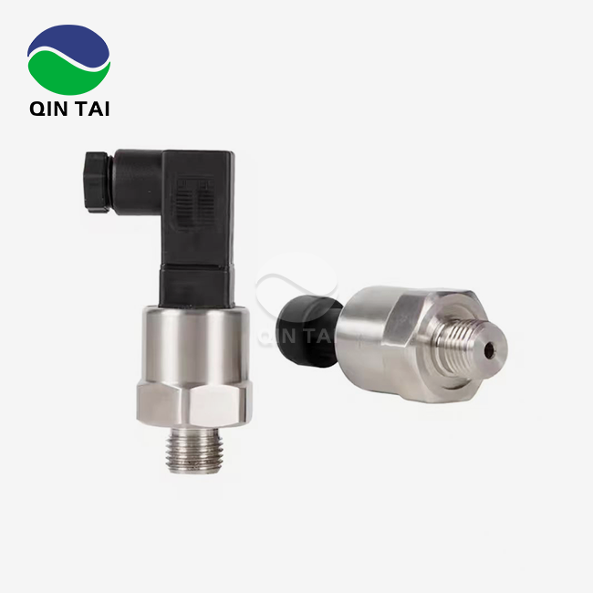
An alumina or zirconia cushion acts as one electrode in capacitive ceramic pressure sensors, which are paired with a set counter-electrode. The ceramic structure is very resistant to chemicals and works with a wide range of media, which is important for exhaust conditions that are corrosive in SCR and DPF systems. Their natural stability across a wide range of temperatures means that results will stay the same without having to be re-calibrated often. This directly meets the needs of diesel engine OEMs for long-term reliability in commercial cars and generator sets.
Through silicon micromachining, MEMS technology shrinks sensor elements, making small devices that handle signals in-house. These sensors use very little power—often less than 10 mW—so they are perfect for IoT systems that run on batteries and wireless tracking networks. Because it has a smaller size, it can be used in places with limited room, like engine compartments for heavy trucks and hydraulic systems for building equipment.
Data Processing and Connectivity Features
Smart sensors have microprocessors that are built in and automatically do linearization, temperature adjustment, and self-calibration. This built-in intelligence gets rid of the need for external filtering circuits, which makes the system simpler and less likely to break. Standard industrial interfaces like CAN bus, Modbus RTU, and IO-Link are used by the sensors to talk to each other. This makes it easy to connect them to current PLC systems.
LoRaWAN, Bluetooth Low Energy, or industrial WiFi wireless connectivity choices let you watch from afar without having to make a lot of changes to your wiring. The ability to do this is especially useful for retrofitting aftermarket uses where the cost of installation work is high. Real-time data transmission helps cloud-based analytics systems, which gives you access to predictive maintenance insights that help parts last longer by finding trends of wear and tear before they break down completely.

Core Benefits of Smart Pressure Sensors for Industry 4.0 Applications
Enhanced Accuracy and Regulatory Compliance
Emission rules, such as the EPA 2026 standards and the Euro VI guidelines, require diesel exhaust aftertreatment systems to have accurate pressure tracking at several places. Smart capacitive pressure sensors are accurate to within 0.25% of the full scale and stable to better than 0.1% per year. Through precise DEF injection control and DPF renewal management, this performance directly allows meeting strict NOx reduction requirements.
Smart sensors have advanced tuning features that solve a problem that keeps coming up in mass production settings. In the past, each sensor had to be calibrated on a separate bench, which caused delays and differences in quality. Modern devices with self-calibration processes cut setup time for production lines by 60% and make sure that thousands of units all work the same way. This is very important for OEM makers who make big trucks and farm equipment on a large scale.
Predictive Maintenance and Operational Efficiency
Pressure sensors become active system health monitors through integration with IoT platforms, changing them from inactive measurement tools. Algorithms look at changes in pressure patterns to find odd ones that could mean that DPF filters are clogged, SCR injectors are failing, or turbochargers are wearing out. Studies on industrial automation show that early spotting lets you do planned maintenance during planned downtime instead of emergency fixes. This cuts down on unplanned equipment breakdowns by up to 35%.
The following features show how smart sensors improve the decision-making process in operations. Maintenance teams are notified by continuous drift tracking when readings stray beyond acceptable limits. This stops fake alarms and part replacements that aren't needed. The sensor's non-volatile memory stores historical data that can be analyzed for forensic purposes during failure reviews. This helps engineers find the root causes of problems and make design changes that fix them. Technicians can check the health of sensors from a distance using wireless connections for remote troubleshooting. This is especially helpful for generator sets used in remote mines or backup power installations.
The total cost of ownership goes down because of these features, which include longer service times and better handling of spare parts inventory. When sensor uptime goes up, callback rates go down, which is good for aftermarket sellers because it means happier customers.
Multi-Industry Versatility and Application Breadth
Smart pressure sensors meet a wide range of needs across the entire heavy-duty equipment environment. In car HVAC systems, capacitive sensors keep an eye on the pressure of the refrigerant and can withstand a lot of shaking, so they can keep giving accurate readings even in business vehicles that are constantly under stress. In electric and hybrid building tools, where every watt counts, their low power use makes battery life longer.
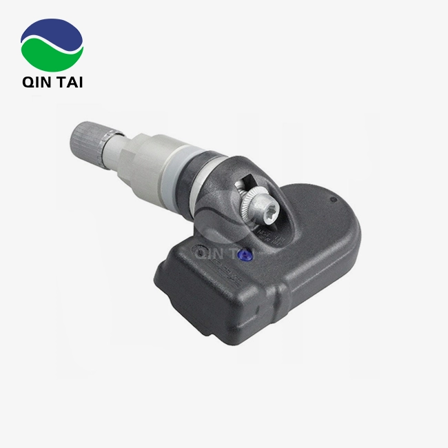
Because MEMS sensors respond quickly, tire pressure tracking systems can find dangerous pressure losses within seconds. This makes fleet workers safer. The automotive-grade approvals, which include the AEC-Q200 rating, make sure that the devices can handle 15 years of thermal cycling and mechanical shocks that are common in heavy truck uses.
In industrial process control settings, things like explosive atmospheres, toxic chemicals, and high or low temperatures can make things difficult. Ceramic capacitive pressure sensors are approved to ATEX and IECEx standards and meet the intrinsically safe design requirements for placements in dangerous areas. Variable frequency drives and high-power switching circuits that are popular in industrial buildings can't mess with their strong construction.
Medical-grade versions of these sensors allow precise control of breathing equipment, but diesel industry suppliers only sell to a small part of this market. Core technology that is improved for medical uses often makes its way back into commercial versions, making them work better overall.

Comparing Smart Pressure Sensors with Traditional Alternatives
Technology Selection Criteria for Different Applications
To choose between capacitive, piezoresistive, and MEMS sensor designs, you need to make sure that the performance traits match the needs of the application. When measuring dynamically, piezoresistive devices work best because their microsecond response times can pick up short-lived pressure jumps during engine combustion cycles. Researchers and developers working on the next generation of diesel engines use these sensors to study burning in great detail and map out turbochargers.
Capacitive ceramic sensors are most common in steady and almost static situations where long-term steadiness is more important than response speed. Ceramic materials are naturally resistant to wander and are compatible with chemicals, which makes them useful for SCR systems that check the pressure of the urea line. Because there are no moving parts, there are no wear mechanisms. This means that the service life is more than 10 years when used continuously, which is a big deal when buying managers look at lifetime costs for fleet applications that run for hundreds of thousands of hours.
MEMS technology fills in the gaps in performance by providing fast enough speed for most control loops while also allowing for smaller sizes and better integration. The batch manufacturing method used in semiconductor fabrication ensures uniform performance from unit to unit at lower production costs compared to standard sensors that are put together one at a time. This way of setting prices makes MEMS devices appealing for OEM uses that need a lot of them, since the price per unit affects how competitive a product is.
Wired Versus Wireless Implementation Considerations
Wireless sensors make installation easier and allow for flexible placement of sensors without having to run wires through sealed chambers. This benefit is especially useful when adding wire connections to old equipment that needs to be taken apart in a lot of pieces. However, technology managers have to think about how to maintain batteries, deal with radio frequency interference, and make sure the network is reliable when using wireless solutions.
Wireless sensors that are driven by batteries work best in situations where checking needs to happen on a regular basis instead of constantly. A generator set tracking system that checks the oil pressure every 10 seconds can run on battery power for more than 5 years, but a DPF differential pressure sensor that feeds the engine ECU needs to be plugged in to make millisecond-level updates. Combining local cable sensors with wireless ports often results in the best solutions, as they keep the control loop intact and allow access to diagnostic data from afar.
Communication delay is another thing that sets them apart. Wired sensors that use CAN bus protocols have set update rates that are in sync with engine control calculations. Wireless sensors, on the other hand, have delays that change depending on network traffic and signal strength. Applications that need to be fail-safe and are safety-critical usually need to be wired and have multiple signal lines.
Procurement Insights for B2B Clients
Defining Technical Specifications for Sourcing
For procurement to go well, technical standards must be clearly stated so that practical needs are aligned with sensor capabilities. The pressure range should cover the expected measurement range plus 20% to protect against damage from overpressure. The accuracy requirements should be based on real control needs, not just theoretical ones. Setting ±0.1% accuracy for a task that only needs ±1% control costs money on precision that isn't needed.
How output signals are formatted affects how hard it is to integrate and how the system is built. Digital protocols (CAN, Modbus) make it possible to get more troubleshooting information and make multi-drop networks easier to set up. Analog voltage or current outputs (0-5V, 4-20mA) work with older systems that already have analog inputs. During the design development process, purchasing managers should make sure that the protocol works with current PLC or ECU platforms. This way, they can avoid having to buy expensive interface converters or make software changes.
Supplier Evaluation and Quality Assurance
The working temperature ranges and environmental standards, such as ingress protection (IP67, IP69K), must meet the worst possible installation circumstances. While pressure washing, water sprays on sensors that are placed in engine spaces. These sensors also experience thermal cycling from cold starts to full load operation and vibration spectra that are very different between mobile equipment and stationary generator sets. When environmental requirements are too small, things break down too soon, which hurts ties with suppliers and the brand's image.
To find suitable suppliers, you have to look at their manufacturing skills, the certifications they hold, and their expert help infrastructure. For basic quality management guarantee, ISO 9001 certification is enough. IATF 16949, on the other hand, is designed to meet the needs of the car industry for advanced quality planning and production part approval processes. Suppliers with these licenses show that they control processes in a structured way and are always looking for ways to improve them.
Testing and validation skills show how skilled a seller is. Ask for proof that there are environmental test rooms for changing temperatures, vibration tables for mechanical testing, and EMC test facilities for making sure the equipment is compatible with electromagnetic fields. Comprehensive approval by suppliers lowers quality risks and speeds up the time it takes to bring new products to market.
When planning production ramps or keeping track of extra supplies, lead time management is very important. Established providers keep extra stock of standard setups, which lets first orders be delivered in two to four weeks and allows consignment inventory plans for OEM relationships with high traffic. It usually takes 8 to 12 weeks for engineering approval and production tooling for custom pressure sensor versions with changed pressure ranges, electrical connectors, or mounting features.
Volume price systems are very different depending on the type of sensor and the number of orders. Because of the way semiconductors work, MEMS sensors have bigger bulk savings. For example, when you buy 1,000 pieces of a sensor, the price of each one drops by 40%. Capacitive ceramic sensors have more steady price drops of about 15 to 20 percent as the number rises, which is because they have different designs for how much it costs to make them. Framework agreements with tiered pricing based on yearly consumption amounts help keep budgets stable and encourage consolidation with chosen suppliers.
Customization and OEM Partnership Models
For many uses, sensors need to be changed beyond what's listed in the catalog in order to work better with other goods or make them stand out. Customization requests often include electrical connectors that don't work with standard wire harnesses, mounting arrangements that work with specific space limitations, and pressure ranges that are set to work within certain working windows. These differences can be easily handled by suppliers who offer full OEM services.
Technical teamwork during the creation of a product cuts down on the time it takes to get to market and makes the design better. Before prototypes are built, suppliers with experienced application engineers give useful advice on where to put sensors, how to fix them, and what kind of signal shaping is needed. This early involvement stops expensive redesigns that are found during validation testing and makes sure that sensors work well in the context of the whole system.
Technical Support and Maintenance for Long-Term Sensor Performance
Installation Best Practices and Common Pitfalls
The dependability and accuracy of pressure sensors depend on how well they are installed. The direction of the pressure port in relation to the flow of the media affects the zero offset and dynamic reaction. This is especially true for liquid applications where readings are skewed by air bubbles that get caught. When you mount sensors so that the process lines face upwards for gas pressure measurement and downwards for liquid uses, air and sediment don't get trapped and build up, which hurts performance.
Grounding and insulation must be done correctly when making electrical links. When sensor signal lines are run next to high-current power cables, they pick up electromagnetic interference that messes up readings. Most noise problems can be solved by keeping them 12 inches away from power cords and using twisted-pair shielded wires with 360-degree connector shell grounding. Stable supply voltage also affects accuracy. Sensors that are designed for 24VDC operation may not work as well when the bus voltage goes below 20V while the engine is starting.
Strain coupling to the detecting element causes measurement mistakes when mechanical force is sent from the mounting structures. When you use flexible mounting seals or vibration isolators, the mechanical path between the sensor body and external vibration is broken. It is very important to follow the torque specs for pressure port fittings exactly. If you overtighten them, the sensor body will bend, and if you undertighten them, leaks and contamination could happen.
Calibration Procedures and Accuracy Verification
Smart pressure sensors can self-calibrate, but measurements should still be checked against reference standards on a regular basis to make sure they are accurate. Setting calibration times based on the severity of the application and government rules makes sure that quality assurance and upkeep costs are equal. Emission-critical sensors that check the pressure of the DEF injection might need to be calibrated once a year, but non-critical tracking points can go up to three years between calibrations.
Calibration starts with verifying the zero offset when there is no pressure, making sure that the sensor output fits the set zero value within acceptable ranges. For full-scale accuracy testing, known pressures are used with deadweight testers or precision pressure calibrators, and sensor output is compared to standards that can be tracked. Multi-point calibration across the measurement range shows linearity mistakes and hysteresis patterns that show the detecting element is wearing out.
By writing down the results of testing, you can keep quality records that help with regulatory compliance and failure analysis reviews. If sensors move too far, they need to be replaced instead of being field adjusted, because damaged sensing elements rarely settle and usually show that failure mechanisms are getting worse. Comparing sensor serial numbers to databases of calibration records lets you plan ahead for replacements when statistical analysis shows that failure is likely to happen.
Software Integration and Firmware Management
To get the most out of smart sensors, central control systems need to be set up correctly. Sensor factors, such as damping time constants, warning limits, and diagnostic allow flags, need to match the needs of the control loop and the design of the operator interface. If you don't set up damping filters correctly, they can cause measurement delays that throw off PID control loops, and alarm levels that are too sensitive can send annoying alerts that operators finally ignore.
Manufacturers of sensors release firmware changes that fix problems that have been found, make the sensors more useful, and make them more compatible with different communication protocols. Setting up processes for managing firmware makes sure that sensors that have already been placed get the benefits of these changes. At the same time, rollout timing is controlled to avoid interruptions in production. Testing firmware changes on non-critical systems before deploying them to all systems lowers the risk, and keeping track of revisions lets you go back if problems arise that were not expected.

Conclusion
Smart pressure sensors are an important tool for meeting Industry 4.0 goals in the areas of making diesel engines, integrating aftertreatment, and maintaining equipment. Their precise measurements, diagnostic intelligence, and ability to connect directly address issues in managing costs, following emission rules, and making sure operations are reliable. Due to their high temperature stability and chemical protection, capacitive ceramic sensors have the performance traits needed for demanding exhaust system uses. If procurement pros know how to choose the right technology, what suppliers can do, and the best ways to put it into action, their companies will be able to get the most out of these advanced sensing solutions and build relationships that will help the products get better over time.
FAQ
How do smart pressure sensors improve emission compliance in diesel engines?
Smart sensors provide the ±0.25% accuracy needed to exactly control the amount of DEF used in SCR systems. This lowers NOx emissions directly to meet EPA and Euro VI standards. Their self-diagnostic features find sensor drift before numbers go out of range, which stops pollution violations and expensive legal violations. Real-time data logging makes audit trails that show compliance during certification testing and operation in the field.
What factors influence long-term sensor accuracy?
Temperature is the main cause of accuracy loss, but reactive ceramic designs make them less sensitive to temperature because of the way the materials are made. Chemical attack resistance is based on how well the media works with the attack; strong exhaust condensates break down materials that aren't meant to be sensors. When designs don't have enough structural support, mechanical vibration speeds up wear breakdowns. Many external stresses that affect accuracy over time can be lessened by installing things correctly and following the manufacturer's instructions.
Can pressure sensors be customized for specific OEM applications?
Electrical connections, mechanical mounting, pressure ranges, and output data formats can all be fully customized. Development times are usually between 8 and 12 weeks for normal goods that are changed and between 16 and 24 weeks for completely new designs. To warrant investing in tools, the minimum order quantity for custom versions is usually between 500 and 1,000 pieces per year. However, if an OEM has a long-term relationship with the company, they may be able to reach lower limits.
Partner with Qintai for Advanced Pressure Sensor Solutions
Xi'an Qintai Automotive Emission Technology brings over two decades of specialized experience in diesel engine aftertreatment sensors, serving as the leading OEM pressure sensor supplier to China's top engine manufacturers including Weichai Power and Yuchai Power. Our ISO 9001, IATF 16949, and CMC certified manufacturing facilities produce capacitive ceramic pressure sensors engineered specifically for harsh exhaust environments, delivering the accuracy and durability that emission compliance demands. With 58 invention patents and comprehensive OEM/ODM capabilities, we customize sensor solutions matching your exact technical specifications and production volumes.
Technical teams access our independent R&D expertise for application engineering support, while procurement managers benefit from competitive pricing structures designed for long-term partnerships. Contact info@qt-sensor.com to discuss your pressure sensor requirements, request detailed datasheets, or schedule technical consultations with our applications engineers who understand the unique challenges facing diesel equipment manufacturers in global markets.
References
1. Zhang, L., & Martinez, R. (2023). Smart Sensor Technologies for Industrial Automation: Principles and Applications. Industrial Press.
2. European Commission Joint Research Centre. (2024). Emission Control Technologies for Heavy-Duty Diesel Engines: Technical Reference Guide. Publications Office of the European Union.
3. Anderson, K. J. (2023). Capacitive Pressure Sensors in Harsh Environment Applications. Journal of Sensor Technology and Applications, 18(4), 112-128.
4. International Society of Automation. (2024). Industry 4.0 Sensor Selection and Integration Handbook. ISA Publications.
5. Peterson, D. M., & Wong, H. C. (2023). Predictive Maintenance Strategies Using Smart Pressure Sensors in Commercial Vehicle Fleets. International Journal of Automotive Engineering, 42(2), 89-104.
6. Society of Automotive Engineers. (2024). SAE J1939 Network Communication Standards for Heavy-Duty Applications. SAE International Technical Standards.


Our customers’ satisfaction speaks for our quality — contact us to experience the same reliable service.