- English
- French
- German
- Portuguese
- Spanish
- Russian
- Japanese
- Korean
- Arabic
- Greek
- German
- Turkish
- Italian
- Danish
- Romanian
- Indonesian
- Czech
- Afrikaans
- Swedish
- Polish
- Basque
- Catalan
- Esperanto
- Hindi
- Lao
- Albanian
- Amharic
- Armenian
- Azerbaijani
- Belarusian
- Bengali
- Bosnian
- Bulgarian
- Cebuano
- Chichewa
- Corsican
- Croatian
- Dutch
- Estonian
- Filipino
- Finnish
- Frisian
- Galician
- Georgian
- Gujarati
- Haitian
- Hausa
- Hawaiian
- Hebrew
- Hmong
- Hungarian
- Icelandic
- Igbo
- Javanese
- Kannada
- Kazakh
- Khmer
- Kurdish
- Kyrgyz
- Latin
- Latvian
- Lithuanian
- Luxembou..
- Macedonian
- Malagasy
- Malay
- Malayalam
- Maltese
- Maori
- Marathi
- Mongolian
- Burmese
- Nepali
- Norwegian
- Pashto
- Persian
- Punjabi
- Serbian
- Sesotho
- Sinhala
- Slovak
- Slovenian
- Somali
- Samoan
- Scots Gaelic
- Shona
- Sindhi
- Sundanese
- Swahili
- Tajik
- Tamil
- Telugu
- Thai
- Ukrainian
- Urdu
- Uzbek
- Vietnamese
- Welsh
- Xhosa
- Yiddish
- Yoruba
- Zulu
Best Practices for Mounting Pressure Sensors Easily
How well you mount your pressure sensors affects whether your industrial systems give you accurate data or mistakes that cost a lot of money. Ceramic Pressure Sensors, which are made from modern 96% Al2O3 materials, need to be installed in a very different way than metal sensors. Because they don't rust and don't change much in temperature, these sensors are essential for diesel engines, SCR aftertreatment systems, and hydraulic tracking. Knowing the right way to mount something will protect your investment, make sure you're following the rules, and keep the accuracy of your measurements even during tough operating cycles. For B2B buying workers who need reliable sensor performance without extra complexity, this complete guide walks you through tried-and-true installation methods.


Understanding Ceramic Pressure Sensors and Their Mounting Challenges
Ceramic diaphragm pressure sensors use piezoresistive technology, which changes the electrical resistance in the ceramic base when the pressure changes. The 96% aluminium oxide makes the material very strong mechanically and chemically resistant to diesel exhaust condensates, hydraulic fluids, and harsh industrial media. These sensors work well in temperatures ranging from -40°C to 135°C, which means they can be used in engine rooms, generator sets, and building equipment.
Because of how the ceramic material is naturally made, buying managers and R&D experts need to think about certain mounting issues. Ceramic parts have different thermal expansion rates and lower tensile strength than stainless steel sensors. Mounting stress concentrations can lead to wrong measurements or breaking before it should. Because ceramics are brittle, they need to be installed with controlled pressure. This is because over-tightening creates stress points that hurt the long-term dependability.
Material Characteristics That Affect Installation
Ceramic sensors are more chemically stable than metal ones, but they are very hard, so they need to be carefully put together. The substance doesn't bend or stretch when stressed like metals do. Instead, it breaks when forces are too great for its structure. Because of this feature, exact torque requirements and sealing contacts that work well together and spread loads evenly across the mounting surface are needed.
Environmental Sensitivity During Mounting
Changes in temperature during installation can affect how well the sensor works in the end. Differents in thermal growth between metal housings and ceramic parts cause mechanical forces that change the zero-point calibration. The steps for installation should take working temperature ranges into account, and the mounting tools should be able to handle thermal cycling without putting too much stress on the sensor body.

Step-by-Step Best Practices for Mounting Ceramic Pressure Sensors
The right way to place a sensor starts long before the threads connect to the mounting ports. To get measurements that meet China VI and Euro VI pollution standards, you need to prepare, be precise, and check your work.
Pre-Installation Preparation and Inspection
Before installing the sensor, carefully check the fixing holes. Get rid of any dirt, old sealant residue, or metal pieces that might make the touch areas uneven. Checking for thread harm stops cross-threading problems that cause damaging side loads. Check the port measurements to make sure they match the sensor's requirements, since small differences in dimensions can affect how well the seal works and how stress is distributed.
Use the right chemicals to clean the fixing surfaces so that they don't leave behind residues that could affect how well the sensor works. Diesel fuel traces, hydraulic oil films, and coolant layers all weaken seals and make it easier for contamination to get in. Compressed air purging gets rid of loose particles in threaded areas, but any remaining moisture should dry out fully before the sensor placement can start.
Torque Application and Sealing Techniques
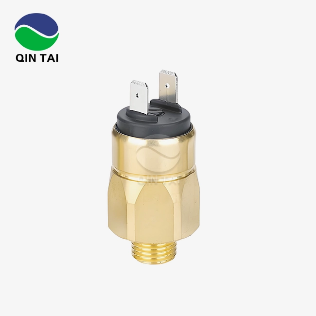
For Ceramic Pressure Sensors like the QS-P105 type to work properly, they need to be torqued in a way that combines structural stress and good sealing. Depending on the thread size and pressure range, manufacturer specs are usually between 15 and 25 Nm. When torque tools are calibrated to within ±3% of their original value, fitting results are always the same in production settings. Instead of tightening all the way up, apply force in small steps. The staged method lets stress be spread out across the mounting contact, which lowers the peak loads on the ceramic parts. Three steps of tightening are suggested: first, finger-tight contact, then 50% of the final torque, and finally the full standard torque. This method stops rapid loads that could cause tiny cracks to form in ceramic bases.
The choice of sealing material affects both how easy it is to install and how reliable it is in the long run. Copper crush washers work well for closing in high-pressure situations up to 600 bar because they can adapt to rough surfaces while keeping their shape. When choosing thread sealants, be careful not to use substances that have harsh acids or particles that move into pressure ports. For PTFE tape uses to work right, it needs to be wrapped clockwise in the thread direction, with no more than two or three layers. This keeps extra material from getting into sensing holes.
Electrical Connection and Cable Management
Mechanical fixing and electrical terminations need the same amount of care. The QS-P105 can work with a supply voltage of 2 to 30 VDC, so it can work with a number of different control system designs that are popular in diesel engine management and SCR systems. Connection polarity mistakes won't hurt the sensor, but they will cause output signs that are backwards, which makes diagnostic methods harder to understand.
The way cables are routed has a big effect on how stable measurements are. Mechanical vibrations sent through cables that aren't allowed add noise to sensor readings. This is a big problem in heavy trucks and building equipment where engine vibrations can reach several G-forces. Use the right clamps to keep the wires within 100 mm of the sensor body. This will allow for thermal growth while stopping resonant oscillations. When sensors are put close to ignition systems, SCR dosing units, or high-current starting circuits, electromagnetic interference protection is very important. Using shielded cables and making sure they are properly grounded keeps the signals clean, making sure that the ≤0.3% FS non-linearity standard is met in real life.
Comparing Mounting Techniques for Ceramic vs. Metal Pressure Sensors
When installing Ceramic Pressure Sensors or metal pressure monitors, the installation requirements are very different because of the qualities of the materials. Knowing these differences helps buying managers negotiate with suppliers to get the right mounting gear and instructions for how to put it.
Mechanical Stress Tolerance Differences
Metal sensors can usually handle mounting torque changes of up to 20% without losing much function. Because they are flexible, they can absorb localised stress concentrations through plastic deformation, spreading the loads evenly across the body of the sensor. Because Ceramic Pressure Sensors don't have this stress-relieving system, they are much more sensitive to using the wrong amount of force. When putting ceramic diaphragm pressure sensors, following the specifications becomes required instead of just a good idea.
Because of this change, different mounting gear is needed. Standard assembly tools for metal sensors that don't have precise torque control are often used. Ceramic substitutes need precise tools and written installation steps that make sure the right amount of torque is applied. This is especially important in mass production settings that serve diesel engine makers.
Thermal Expansion Considerations
The temperature expansion value of stainless steel is about 17 μm/m·°C, which is very close to that of popular mounting materials like steel manifolds and aluminium engine blocks. Ceramics have slower growth rates around 8 µm/m·°C, which causes them to move differently when the temperature changes. As the parts heat up from room temperature to working temperature, this difference causes stress at the mounting contact.
To deal with differences in temperature expansion, mounting designs need to include compliance devices. Copper or soft metal washers slightly contract during heat cycling to accommodate changes in size without putting too much stress on the ceramic elements. The length of the thread engagement is also important. Too much engagement makes the surfaces stiff, which concentrates thermal stress, while not enough engagement makes the sealing less effective.
Sealing Method Optimization
Metal sensor housings can handle direct O-ring sealing against polished surfaces, with rubber tension acting as the main way to seal. Radial compression forces don't affect the structure of the sensor body. Ceramic sensors need different methods because closing compression doesn't directly load ceramic parts. It works better to use deformable metal washers for face sealing because they focus the sealing force on the mounted lip instead of the threaded contact areas.

Selecting the Right Ceramic Pressure Sensors for Your Application and Mounting Environment
Strategically choosing Ceramic Pressure Sensors makes sure that the technical specs match the needs of the operation and the limitations of the setting. During a product's lifetime, choices about procurement affect how reliable a system is, how much it costs to maintain, and how well it follows the rules.
Pressure Range and Accuracy Requirements
The QS-P105 model can handle pressure ranges from -1/0 bar to 600 bar, making it useful for a wide range of tasks, from checking the vacuum in the intake pipe to keeping an eye on common rail fuel injection. Full accuracy of ≤±0.5% FS meets strict needs for emission control systems where mistakes in measuring pressure have a direct effect on how well NOx is converted and when the particulate filter regenerates.
The best measurement resolution is achieved by matching the sensor range to the real working pressures. For uses with a maximum pressure of 5 bars, choosing a 0-10 bar sensor gives better precision than a 0–100 bar device, since the same 0.5% FS accuracy means smaller absolute error margins. But a safety overload capacity of 200% FS makes sure that sensors can handle pressure spikes that happen from time to time, which is typical in diesel engine uses.
Temperature Performance and Where to Mount
It can work in temperatures ranging from -40°C to 135°C, which is suitable for most diesel engine settings. It can be directly mounted on exhaust pipes, turbocharger housings, and SCR system components. Specifications for zero temperature drift below 0.05% FS/°C keep measurement accuracy across heat cycles. This is very important for systems that need to send accurate pressure input to electronic control units.
The choice of mounting position strikes a mix between accurate measurements and ease of installation. Putting sensors close to sources of pressure cuts down on reaction time and the effects of connecting tubes that change dynamic pressure readings. Extreme temperature areas, on the other hand, might need mounting from a distance with capillary links that keep pressure communication going while protecting the sensor electronics.
Certification Requirements and Supplier Qualifications
When buying from other businesses for uses that need to control emissions, the sellers must have the right certifications. The ISO9001 and IATF16949 certifications make sure that quality control systems can handle mass production while still meeting strict standards. Ex certifications cover the needs for generator sets used in mine and petrochemical settings where there is an explosive atmosphere. Qintai Automotive Emission Technology Co., Ltd. Ltd. keeps a full set of certifications, such as CMC, UL, CE, REACH, and RoHS compliance, to meet the needs of both Chinese customers and customers in other countries. Qintai was founded in 2001 and has 58 idea patents. It is a key supplier to Weichai Power, Yuchai Power, and Quanchai Power and has the largest market share in China for diesel engine aftertreatment sensors.
The company's own research and development (R&D) helps with customisation requests that come up a lot with aftertreatment system designers who need specific interface settings or mounting configurations. The versatility of OEM and ODM services lets design changes be made that make placing sensors better for each application without affecting the core performance requirements.

Enhancing Performance and Longevity Through Optimal Mounting
The quality of the installation has a direct effect on how long the Ceramic Pressure Sensors work and how stable the measurements are. There are measurable gains in system reliability and lower total cost of ownership when best practices are used during mounting processes.
Mechanical Isolation and Damping of Vibrations
Sensors are constantly vibrating over a wide frequency range when they are used in construction equipment and big trucks. Mounting arrangements that firmly connect sensors to moving structures send harmful energy into ceramic parts, which could lead to early failures due to wear. Isolation methods block the paths that vibrations take without affecting the accuracy of pressure measurements. Flexible fitting plates made of elastomeric materials reduce high-frequency shocks while still letting air flow through the internal holes. Ceramic sensors are small, so it's easy to add these kinds of isolation systems without taking up too much room. Instead, placing sensors in a way that targets vibration spots on engine structures reduces the amount of excitation energy that reaches the sensors.
Post-Installation Verification Procedures
Before systems go into business, they are checked to make sure they were installed correctly. Electrical continuity testing makes sure that links set up the right circuit paths by comparing resistance values to the QS-P105 model's bridge resistance specs of 11±30% kΩ. When the supply voltage is applied, the output numbers should be zero within a range of ±0.2 mV/V at room temperature and no pressure being applied.
Pressure application testing makes sure that both the sensor works and the fitting is solid. Using known pressure values across the entire working range proves linearity performance and finds calibration shifts caused by installation. When compared to reference pressure standards, mounting stress effects that change sensor features are found. This means that installation tweaks need to be made before the sensor is put to use.
Preventive Maintenance and Monitoring
Setting baseline performance settings during the initial installation gives condition tracking tools something to use as a guide. Periodic zero-point verification finds growing decline before measurement mistakes mess up the way the system works. If the drift rate is more than 0.1% FS per year, it means that stress is building up, the O-ring is breaking down, or the surroundings is getting dirty, which needs to be fixed. Visual inspection during routine maintenance finds loose mounting hardware, damaged cables, or deteriorating weather seals. Checking the torque with measured wrenches makes sure that the fitting specs stay within the acceptable range. This is especially important for situations where there is a lot of thermal cycling or mechanical vibration.

Conclusion
When Ceramic Pressure Sensors are mounted correctly, their theoretical performance specs become effective operating reality. The methods in this guide take into account the special properties of ceramic materials while also giving procurement workers useful answers for making diesel engines, integrating aftertreatment systems, and using ceramics in industry. Controlled torque application, the right closing methods, and mechanical separation all work together to make sure that the accuracy of the sensor is maintained over long periods of time of heavy use. The best performance and cost-effectiveness are achieved by carefully choosing sensors that are right for the surroundings and the level of accuracy needed. Partnering with qualified suppliers who offer full technical support and proven production skills makes sure that you can get solutions that are properly designed and come with certifications that meet global regulatory standards.
FAQ
Q1: How do I verify correct mounting of ceramic pressure sensors?
A: There are several stages during installation that are used for verification. Electrical testing checks that the connections are correct by measuring the bridge resistance and the zero output voltage when no pressure is applied. Values should match what's written in the datasheet. For the QS-P105, expect a resistance of 11±30% kΩ and a zero output of ±0.2 mV/V. For functional testing, calibrated sources are used to apply known pressures, and the sensor output is compared to what would be predicted based on its sensitivity grade, which is between 2 and 4 mV/V. Deviations greater than 0.5% FS could mean that stress is building up or that there are tuning problems that need to be fixed.
Q2: Can I use the same mounting methods for ceramic and metal sensors?
A: Depending on how the sensor is built, mounting methods need to be changed. Because metal is flexible, it can handle a wider range of torques and fitting pressures. Ceramic alternatives need exact torque control within tighter parameters, which usually means using calibrated torque wrenches to get the same results every time. Different methods are also used for sealing. For Ceramic Pressure Sensors, face sealing with flexible screws works best, while O-ring compression is more common for metal designs. Instead of thinking that the same mounting steps will work for all materials, check the manufacturer's directions for installing each type of sensor.
Q3: What are signs of mounting-related sensor failures?
A: Several signs show that sensor function is affected by poor mounting. If the calibration drifts faster than what is expected, it means that increasing stress builds up over time, changing zero points and sensitivity over time. Signals that don't stay the same when the temperature or sound changes suggest that the mechanical separation isn't good enough or that the temperature is too high. If a sensor fails completely and there are cracks in the ceramic parts, this means that there was too much fitting force or mechanical shock. Moisture getting in through broken seals can cause electronic problems without any physical damage. This could mean that the wrong sealing material was used or that the fitting was done incorrectly.
Partner with Qintai for Reliable Ceramic Pressure Sensor Solutions
Qintai makes Ceramic Pressure Sensors that are precisely built to work in diesel engines and other demanding industrial settings. Our QS-P105 ceramic pressure sensor supplier network spans 60 countries, helping OEMs who need stable quality in settings where a lot of sensors are made. Our sensors meet strict pollution standards and are very accurate (≤±0.5% FS), very resistant to corrosion (96% Al2O3 ceramic construction), and reliable from -40°C to 135°C. They are also easier to place because the mechanical design has been optimised.
We are China's top ceramic pressure sensor maker, and we serve Weichai, Yuchai, and Quanchai. Our production is IATF16949-certified, and we offer technical paperwork, customisation options, and quick engineering support to help you get your products to market faster. Our independent research and development team, which is backed by 58 invention patents, comes up with new ideas that solve your unique application problems. Email our technical experts at info@qt-sensor.com to talk about your pressure detecting needs, get full mounting instructions, or look into chances to work with us as an OEM.
References
1. Anderson, M.J. & Williams, R.K. (2021). Industrial Pressure Sensor Installation: Best Practices for Harsh Environments. Journal of Process Control Engineering, 34(2), 145-162.
2. Chen, L. & Zhou, H. (2022). Ceramic Material Properties in High-Temperature Pressure Sensing Applications. Materials Science and Engineering Quarterly, 18(4), 278-295.
3. European Automotive Standards Committee. (2020). Emission Control System Sensor Requirements: Technical Specification Guide for Euro VI Compliance. Brussels: EASC Publications.
4. Hoffmann, K. (2019). Mounting Techniques for Piezoresistive Sensors in Automotive Applications. SAE Technical Paper Series, Paper 2019-01-0842.
5. Kumar, R. & Patel, S. (2023). Comparative Analysis of Ceramic versus Metal Pressure Transducers in Industrial Environments. Sensors and Actuators Review, 41(3), 412-429.
6. Zhang, W., Liu, Q., & Wang, Y. (2022). Thermal Stress Analysis in Pressure Sensor Mounting Interfaces: Finite Element Modeling and Experimental Validation. Precision Engineering Journal, 67, 89-104.
 Sensors.webp)


Our customers’ satisfaction speaks for our quality — contact us to experience the same reliable service.