- English
- French
- German
- Portuguese
- Spanish
- Russian
- Japanese
- Korean
- Arabic
- Greek
- German
- Turkish
- Italian
- Danish
- Romanian
- Indonesian
- Czech
- Afrikaans
- Swedish
- Polish
- Basque
- Catalan
- Esperanto
- Hindi
- Lao
- Albanian
- Amharic
- Armenian
- Azerbaijani
- Belarusian
- Bengali
- Bosnian
- Bulgarian
- Cebuano
- Chichewa
- Corsican
- Croatian
- Dutch
- Estonian
- Filipino
- Finnish
- Frisian
- Galician
- Georgian
- Gujarati
- Haitian
- Hausa
- Hawaiian
- Hebrew
- Hmong
- Hungarian
- Icelandic
- Igbo
- Javanese
- Kannada
- Kazakh
- Khmer
- Kurdish
- Kyrgyz
- Latin
- Latvian
- Lithuanian
- Luxembou..
- Macedonian
- Malagasy
- Malay
- Malayalam
- Maltese
- Maori
- Marathi
- Mongolian
- Burmese
- Nepali
- Norwegian
- Pashto
- Persian
- Punjabi
- Serbian
- Sesotho
- Sinhala
- Slovak
- Slovenian
- Somali
- Samoan
- Scots Gaelic
- Shona
- Sindhi
- Sundanese
- Swahili
- Tajik
- Tamil
- Telugu
- Thai
- Ukrainian
- Urdu
- Uzbek
- Vietnamese
- Welsh
- Xhosa
- Yiddish
- Yoruba
- Zulu
Ceramic Pressure Sensors vs Silicon: Which Is Best for Industry?
When choosing between ceramic and silicon pressure sensors for industrial applications, ceramic pressure sensors typically offer superior durability and chemical resistance, making them ideal for harsh environments in diesel engines, hydraulic systems, and industrial automation. Silicon sensors excel in precision and cost-effectiveness for controlled settings. The decision hinges on your operational environment, temperature extremes, media compatibility, and total cost of ownership. Ceramic technology stands out when long-term reliability, corrosion resistance, and high-pressure capability matter most—especially in heavy-duty machinery and emission control systems where downtime is costly and regulatory compliance is non-negotiable.
Introduction
Choosing the right pressure sensor technology has a direct effect on how well machinery works, how much it costs to maintain, and how well it follows the rules in all workplace settings. The sensor you choose affects how accurate your measurements are, how long your system works, and how safe it is to use, whether you're in charge of diesel engine aftertreatment systems, hydraulic machinery, or generator sets.
This in-depth comparison looks at ceramic and silicon pressure sensors in the context of real-world industrial needs. It helps purchasing managers, research and development engineers, and technical decision-makers figure out which technology best meets their needs. Knowing the properties, performance, and application fit of a material lets you make buying choices that lower the total cost of ownership while still making sure it works well in the toughest circumstances.
Understanding Ceramic and Silicon Pressure Sensors
Operating Principles and Material Science
Ceramic Pressure Sensors use piezoresistive or capacitive sensing methods and 96% Al2O3 ceramic diaphragms that change resistance or capacitance when the pressure changes. This thick-film ceramic construction is very strong mechanically and doesn't react with chemicals. Silicon sensors work mostly on piezoresistive principles. They combine semiconductor technology with micromachined silicon diaphragms that are very sensitive but need to be protected in harsh environments. The main difference is how strong the materials are. Diesel exhaust, hydraulic fluids, and industrial chemicals can't break down ceramic because of its crystalline structure. Even though silicon sensors produce great signals, they can drift when they are wet or when they go through the thermal stress cycle that is common in heavy-duty uses.
Construction and Design Architecture
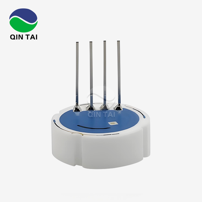
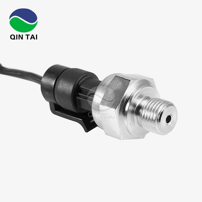
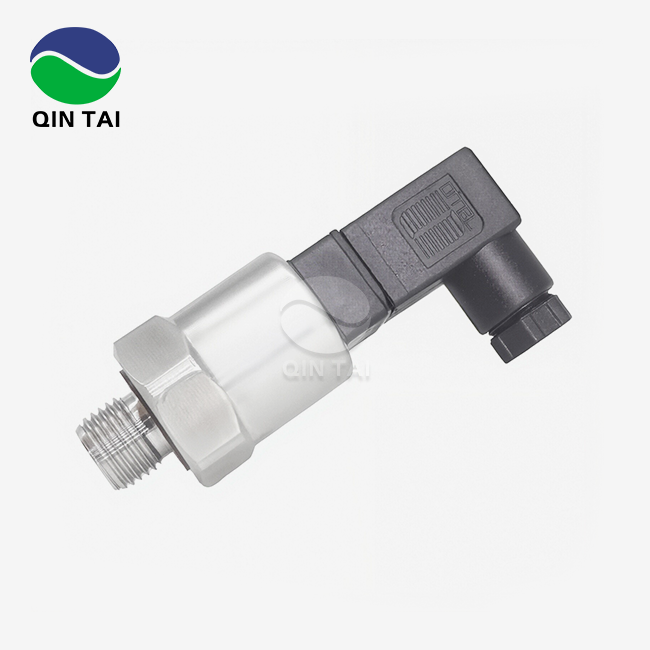
Ceramic sensors made today have small shapes and easier-to-use mounting interfaces. This method is shown by the QS-P105, which has a strong ceramic element housed in a way that makes it easy to install in tight spaces like those found in engine blocks and hydraulic manifolds. Silicon sensors usually have signal processing devices built right into the sensor package. This gives you digital output options, but it might limit the temperature ranges where the sensor can work.
When it comes to retrofit and OEM uses, installation freedom is very important. Ceramic sensors can work with different pressure port configurations without losing accuracy, so they can be mounted on a wide range of platforms for construction and farming equipment. This adaptability makes it easier for aftermarket providers who deal with different kinds of tools to keep track of their supplies.
Performance Comparison: Ceramic vs Silicon Pressure Sensors
Accuracy and Long-Term Stability
Ceramic Pressure Sensors keep measuring accurately for long periods of time. Their non-linearity specs at ≤ 0.3% full scale stay the same after millions of pressure cycles. The QS-P105 is very accurate, with a full range of ≤ ±0.5% FS from -1 bar to 600 bar. It meets strict standards for tracking emission control systems, where sensor drift can cause false fault codes and compliance failures. While silicon sensors may be as accurate at first as ceramic designs, their accuracy can change over time if they are exposed to thermal cycling between -40°C and 135°C, which is common in diesel engine environments. This drift means that calibrations have to be done more often, which increases the cost of maintenance and could cause the system to go down during important operations.
Temperature Performance and Environmental Robustness
The operating temperature range makes these systems very different. Ceramic sensors work accurately from -40°C to 135°C, and they have to have zero temperature drift specifications of less than 0.03 to 0.05% FS/°C, based on the pressure range. This thermal stability is very important in generator set applications where changing temperatures outside and engine heat make things tough. Chemical similarity is another important factor. Ceramic's surface is inert, so sulfur compounds in exhaust gasses, corrosive hydraulic additives, and aggressive media used in industrial processes can't damage it. When measuring corrosive media, silicon sensors need protective coatings or isolation diaphragms. This makes the design more complicated and adds a possible failure point that ceramic designs don't have.
Durability and Overload Protection
For ceramic sensors, the safety overload capacity at 200% full scale protects against pressure spikes that happen when the hydraulic system starts up or when the engine goes through sudden conditions. This ability to handle overload and its high resistance to wear from media full of particles makes the sensor last a lot longer than silicon-based options in areas where contamination is inevitable, like in building and mining equipment. Ceramics made of 96% Al2O3 are very strong and can handle pressure, shock, and mechanical stress without breaking. This toughness means that sensors are less likely to fail in mobile equipment where they are constantly being loaded mechanically. This is a benefit in terms of reliability that procurement managers know lowers warranty claims and field service costs.
Application Suitability: Which Sensor Fits Your Industry?
Diesel Engine Aftertreatment Systems
Emission control systems need monitors that work the same way no matter what the engine is running on and meet China VI and Euro VI standards. Ceramic Pressure Sensors work great in SCR and DPF systems because they can correctly measure urea injection pressure, exhaust backpressure, and filter difference pressure. They can also handle high-temperature exhaust gasses and chemicals that are present in ammonia compounds without breaking down.
The QS-P105 has a wide pressure range that lets it support multiple measurement points within a single aftertreatment design. This makes it easier for OEM makers to keep track of their inventory and makes sure that the device works with a variety of engine platforms. This adaptability is important when the need for mass output and standards affects the choice of component.
Hydraulic and Pneumatic Systems
Accurately tracking hydraulic pressure is important for construction and farming tools to sense load, protect circuits, and get the best performance. Ceramic sensors can handle hydraulic oil additives, changes in temperature, and amounts of contamination that make silicon sensors last less long. Their small size makes it easier to put them into valve blocks and actuator assemblies that are already full, where space limitations limit the number of sensors that can be used. System integrators like that ceramic sensors have interfaces and parameter configurations that can be changed to fit different hydraulic control architectures without having to do a lot of redesigning. Established suppliers that can deliver quickly help keep project deadlines tight and keep production delays to a minimum.
Generator Set and Backup Power Applications
For industrial generators to work reliably for a long time, they need sensors that have been tested and shown to last. This is especially true for important backup systems and mines. Because ceramic technology is resistant to humidity, temperature changes, and vibration, it can be used to reliably monitor pressure in fuel systems, lubrication circuits, and cooling systems for 10 to 15 years. Major diesel engine makers endorsing a brand shows that ceramic sensors are reliable in mission-critical settings where sudden failures can have very bad results. Because of this track record, technical experts are sure that ceramic sensors will meet the dependability needs of industrial applications.
Aftermarket and Service Applications
Repair shops, dealers, and parts providers that work with industrial vehicles and construction equipment aftermarkets prefer sensors that are cost-effective, can be used in a wide range of situations, and are easy to install. Ceramic sensors meet these requirements and have lower long-term failure rates than other options. This means that customers will be happier and the guarantee will be more secure. Ceramic sensors can be used with a variety of equipment types, which helps with managing in-stock inventory and keeps capital from getting stuck in too many SKUs and specialized parts. Installation time is cut down by easy mounting configurations, which lets service technicians fix things quickly and get the equipment back to making money.
Procurement and Cost Considerations for B2B Buyers
Total Cost of Ownership Analysis
Ceramic sensors may be more expensive to buy at first than silicon alternatives, but a full lifetime study shows that they save a lot of money because they last longer, need less upkeep, and fail less often. To figure out the total cost of ownership, you have to take into account how often you have to replace things, how long they need to be calibrated, and how much it costs to have them down for repairs. In these areas, ceramic technology clearly shines in harsh industrial settings.
When purchasing managers look at sensor providers, they should not only look at unit prices, but also how well they can help with technical issues, how reliable their deliveries are, and how much they can customize the products. Suppliers who offer engineering help during specification development and application optimization add value that goes beyond the price of the parts themselves.
Supplier Evaluation and Quality Assurance
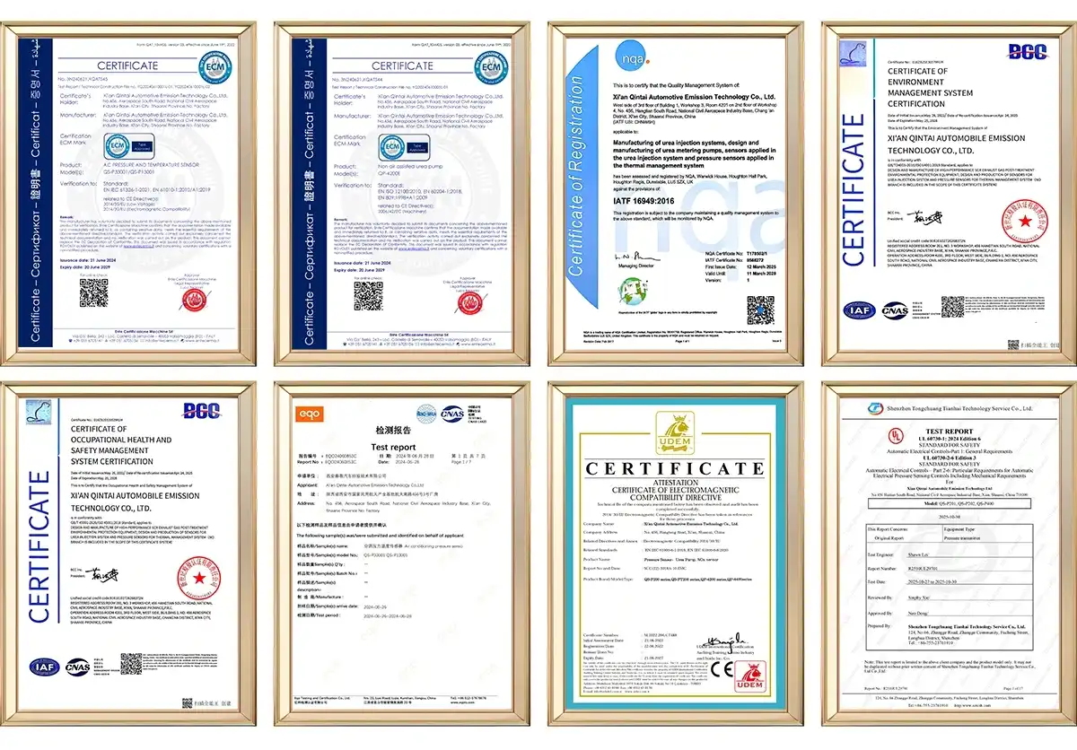
Established ceramic pressure sensor makers keep badges like ISO9001, IATF16949, and industry-specific credentials that show they can make high-quality products and keep an eye on the whole process. These approvals make sure that sensors will work the same way across production lots, which is important for OEM applications that need parts to be able to be switched out and assembly lines to work efficiently, especially when sourcing Ceramic Pressure Sensors for high-volume diesel engine platforms where consistency is paramount.
Checking intellectual property portfolios and patent holdings shows that companies are still investing in research and development and can come up with new technologies. Suppliers who have a lot of patents show that they are dedicated to making technology better and making their products stand out, which helps customers by improving performance and finding solutions that work best for their needs.
Customization and Scale Production
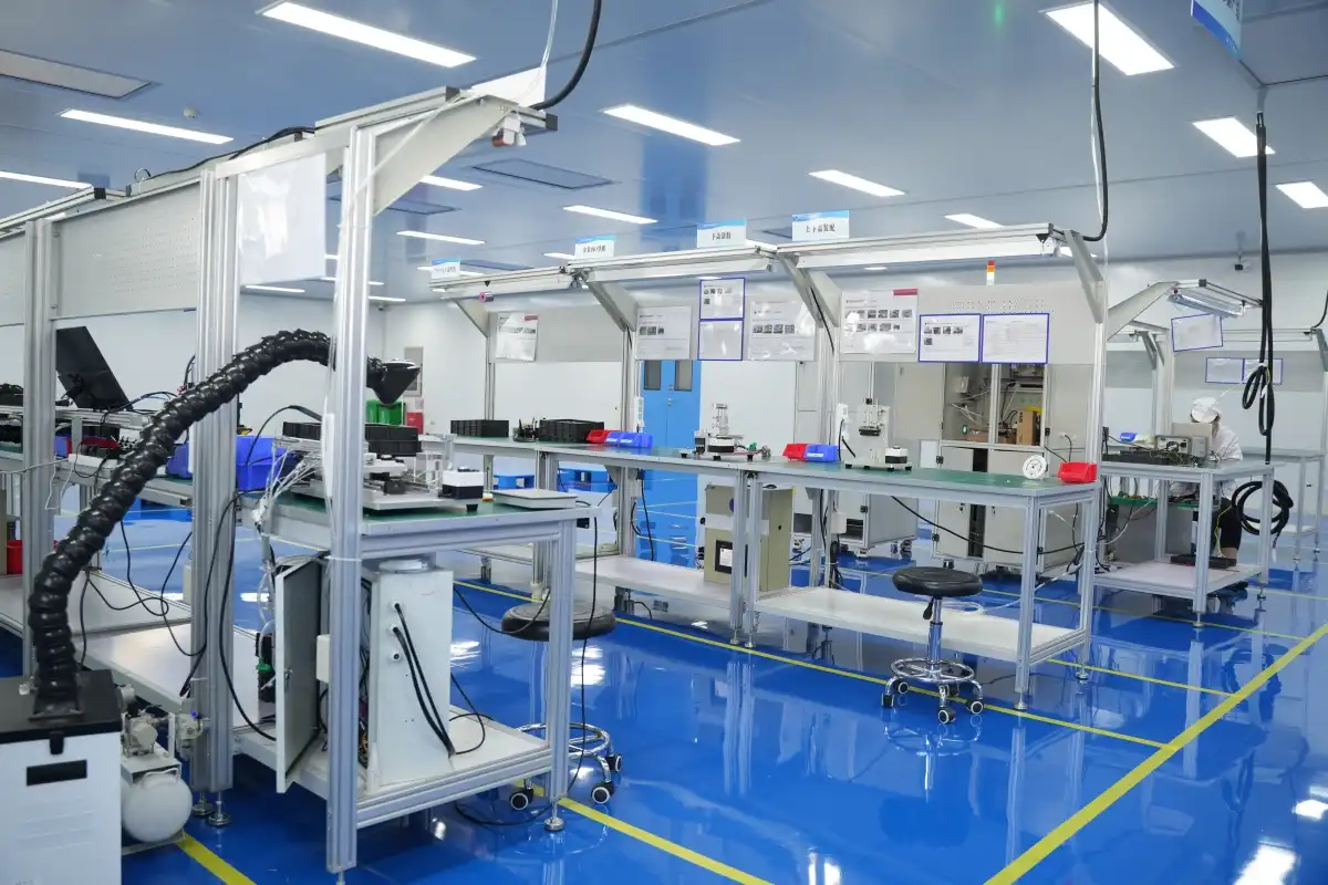
A supplier's mass production capacity shows whether they are a good fit for OEM relationships that need hundreds of thousands of sensors every year. Manufacturers who have dedicated production lines, automatic testing infrastructure, and quality management systems can meet volume needs while still meeting strict tolerances and keeping records that can be tracked. Customization features let sensors be changed to fit different mounting needs, electrical connections, and pressure range requirements, all without having to go through long development processes. Offering OEM and ODM services makes it easier for people to work together to make products. This lets equipment makers get the most out of sensor integration while still meeting cost and efficiency goals in the supply chain.
Installation, Calibration, and Maintenance Insights
Installation Best Practices
The first step in installing a sensor correctly is choosing a place to put it. Avoid places with high shaking levels or temperature differences that are too high for the sensor. Ceramic sensors can work in most industrial settings, but they should be installed with care by following simple rules like using the right torque and staying away from thread contamination that could affect the sealing of the pressure port. It's important to pay attention to how the wires are routed, how they are relieved of stress, and how they are protected from wear and tear or heat. The QS-P105 and other models with a supply voltage range of 2 to 30 VDC can work with a variety of system power designs that are popular in mobile equipment and industrial gear. This makes it easier to integrate electricity across a wide range of platforms.
Calibration and Verification Procedures
The first calibration check makes sure the sensor is accurate by comparing it to reference standards that can be traced back to national metrology institutes. Ceramic sensors usually come factory-calibrated with paperwork that says they have a zero output at ±0.2 mV/V and a sensitivity range of 2–4.0 mV/V. Using precise pressure sources to check the installation in the field makes sure it is working right and sets a standard for future comparisons.
Recalibration times depend on the severity of the application and the rules set by the government. In emission control applications, ceramic sensors may need to be checked once a year to keep up with compliance paperwork. In industrial process applications, calibration cycles could be pushed back to two to three years based on past performance data and stability trends.
Troubleshooting and Maintenance
Most sensor problems are caused by mistakes in the installation process, not by broken parts. Most field problems can be fixed by checking the source voltage, making sure there is good grounding, and making sure water hasn't gotten into the electrical lines. Pressure doesn't usually break ceramic sensors, but they can be damaged if they aren't handled properly when they are being installed or taken out. Instead of repairing sensors, preventive maintenance focuses on checking them. Checking the electrical connections visually, making sure the mounting hardware stays properly torqued, and comparing performance readings to baseline readings on a regular basis can help find problems before they become system failures. This proactive method keeps equipment running as long as possible and stops output from stopping without warning.
Conclusion
To choose between ceramic and silicon pressure sensors, you need to look at the needs of the application and the benefits of each technology. Ceramic Pressure Sensors are the most durable, chemically resistant, and thermally stable sensors on the market. They work best in harsh industrial environments, like diesel engine systems, heavy machinery, and demanding process applications. When accuracy and integration with electrical systems are important, silicon sensors work well in controlled environments. Ceramic technology has strong benefits when long-term dependability, low upkeep, and total cost of ownership are important factors in buying choices. The QS-P105 is a great example of what a modern ceramic sensor can do. It has a strong build and performance specs that meet strict industrial requirements. You can find the best sensor technology for your system's performance and business value by thinking about your operational environment, regulatory requirements, and cost priorities over its entire lifecycle.
FAQ
Q1: What are the main advantages of ceramic pressure sensors over silicon?
A: Ceramic Pressure Sensors are more resistant to rust, can work in a wider range of temperatures, and are very stable over time in tough settings. Because they are chemically inert, they are safe from harsh substances like truck fumes, hydraulic fluids, and industrial chemicals that break down silicon sensors. Ceramic is stronger than metal, so it can handle vibrations and protect against overloading better. This is very important for mobile equipment and high-pressure situations. Ceramic sensors usually last between 10 and 15 years, which cuts down on replacements and lifetime costs by a large amount.
Q2: Are ceramic sensors suitable for high-temperature diesel engine applications?
A: In diesel engine environments, ceramic sensors work consistently in temperatures ranging from -40°C to 135°C, and they keep their accuracy standards even when they are heated and cooled many times. Their temperature drift traits (0.03-0.05% FS/°C) stay the same, unlike silicon sensors, which can experience drift that makes emission control systems less effective. Because it is stable at different temperatures, ceramic technology is perfect for measuring exhaust pressure, controlling the EGR system, and using in aftertreatment systems that need accurate readings even when the temperature changes.
Q3: How do I select the right pressure sensor for my industrial application?
A: When making a choice, you have to think about the pressure range needs, the compatibility with the media, the temperature exposure, the accuracy requirements, and the fitting limitations. Match the sensor pressure range to the operating and peak pressures of the system to make sure it can handle an overload. Check that the material is compatible with the chemistry of the tested media. Make sure that the operating temperature range includes both the atmospheric and process temperatures. Choose an accuracy class that meets the needs of control or regulation. Think about whether the mounting setup will work with the installation area and connection access that you have.
Partner with Qintai for Reliable Ceramic Pressure Sensor Solutions
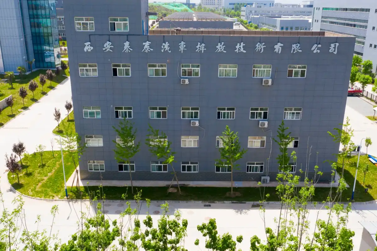
Qintai is an expert at making high-performance Ceramic Pressure Sensors that are made for industry and diesel engines that need to work hard. As China's top original equipment manufacturer (OEM) provider and a valued partner of major engine makers like Weichai Power, Yuchai Power, and Quanchai Power, we offer reliable products backed by ISO9001, IATF16949, and large patent portfolios.
Our QS-P105 type is an example of modern ceramic technology because it has great resistance to corrosion, can handle 600 bar of pressure, and works well in a wide range of temperatures. We provide full OEM and ODM services that can be customized to meet the needs of your unique application. Our production capacity is flexible and can be scaled from small prototypes to large amounts for mass production. Our independent research and development team is always coming up with new ideas to keep up with changing performance and emission standards. Get in touch with our engineering team at info@qt-sensor.com to talk about your ceramic pressure sensor needs and find out how working with an experienced ceramic pressure sensor maker can help your equipment be as reliable and compliant as possible.
References
1. Webster, J. G. (2018). The Measurement, Instrumentation and Sensors Handbook: Spatial, Mechanical, Thermal and Radiation Measurement. CRC Press.
2. Barlian, A. A., Park, W. T., Mallon, J. R., Rastegar, A. J., & Pruitt, B. L. (2009). Review: Semiconductor Piezoresistance for Microsystems. Proceedings of the IEEE, 97(3), 513-552.
3. Tian, B., Zhao, Y., Jiang, Z., Zhang, L., Liao, N., Liu, Y., & Meng, C. (2017). Fabrication and Structural Design of Micro Pressure Sensors for Tire Pressure Measurement Systems. Sensors, 17(2), 355.
4. Frank, R. (2012). Understanding Smart Sensors (3rd ed.). Artech House Publishers.
5. Wilson, J. S. (2005). Sensor Technology Handbook. Newnes Press.
6. Kressmann, R., Klaiber, M., & Honal, M. (2002). Silicon Pressure Sensor with Integrated Signal Conditioning Circuit and Compensation Capability. Sensors and Actuators A: Physical, 97-98, 86-92.


Our customers’ satisfaction speaks for our quality — contact us to experience the same reliable service.