- English
- French
- German
- Portuguese
- Spanish
- Russian
- Japanese
- Korean
- Arabic
- Greek
- German
- Turkish
- Italian
- Danish
- Romanian
- Indonesian
- Czech
- Afrikaans
- Swedish
- Polish
- Basque
- Catalan
- Esperanto
- Hindi
- Lao
- Albanian
- Amharic
- Armenian
- Azerbaijani
- Belarusian
- Bengali
- Bosnian
- Bulgarian
- Cebuano
- Chichewa
- Corsican
- Croatian
- Dutch
- Estonian
- Filipino
- Finnish
- Frisian
- Galician
- Georgian
- Gujarati
- Haitian
- Hausa
- Hawaiian
- Hebrew
- Hmong
- Hungarian
- Icelandic
- Igbo
- Javanese
- Kannada
- Kazakh
- Khmer
- Kurdish
- Kyrgyz
- Latin
- Latvian
- Lithuanian
- Luxembou..
- Macedonian
- Malagasy
- Malay
- Malayalam
- Maltese
- Maori
- Marathi
- Mongolian
- Burmese
- Nepali
- Norwegian
- Pashto
- Persian
- Punjabi
- Serbian
- Sesotho
- Sinhala
- Slovak
- Slovenian
- Somali
- Samoan
- Scots Gaelic
- Shona
- Sindhi
- Sundanese
- Swahili
- Tajik
- Tamil
- Telugu
- Thai
- Ukrainian
- Urdu
- Uzbek
- Vietnamese
- Welsh
- Xhosa
- Yiddish
- Yoruba
- Zulu
How Ceramic Pressure Sensors Handle High Temperature Applications
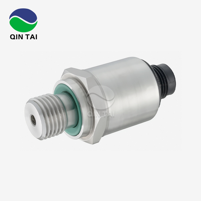
Ceramic Pressure Sensors work really well in hot places because they use modern alumina ceramic materials that keep the structure strong and the measurements accurate when other sensors break. Because 96% Al2O3 ceramic is piezoresistive, it can accurately measure pressure from -40°C to 135°C without drifting or breaking down much. Ceramic Pressure Sensors are essential for diesel engine exhaust systems, generator sets, and industrial process control uses that need to work well under high temperatures because it is resistant to corrosion and has high mechanical strength.
Understanding Ceramic Pressure Sensors and Their High Temperature Capabilities
Material Science Behind Thermal Performance
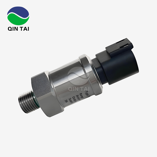
Ceramic Pressure Sensors use the unique qualities of alumina ceramic (Al2O3) to make them more stable at high temperatures. The 96% Al2O3 mix used in industrial-grade sensors like the QS-P105 type doesn't expand or contract much when the temperature changes, so the sensors' dimensions stay the same. This property of the material stops it from deforming mechanically, which can affect the accuracy of measurements in metal diaphragm sensors.
Ceramics have a piezoresistive effect that lets them directly change pressure into an electrical signal. When the ceramic diaphragm is compressed, changes in resistance inside the material cause a voltage output that is proportional to the pressure. Piezoresistive Ceramic Pressure Sensors accurately measure both static and dynamic pressure, while piezoelectric sensors only measure dynamic pressure. The ceramic base has a thick-film resistor network built into it. This network has a sensitivity range of 2 to 4 mV/V and an accuracy of 0.3% full scale.
Temperature Coefficient Performance
In high-heat situations, measurement drift caused by temperature is a major concern. By carefully choosing the materials and making the sensors, high-quality Ceramic Pressure Sensors can keep the temperature from changing by more than 0.05% FS/°C. This level of performance makes sure that a sensor reading 100 bar pressure has an apparent shift of less than 0.05 bar for every degree Celsius change in temperature.
The calibration process takes thermal effects into account by describing how the sensor works across its full working temperature range. From -40°C to 135°C, multi-point temperature compensation keeps output signals accurate by changing them. This compensation method takes into account both changes in the zero point and changes in the span, so the numbers are always the same no matter what the environment is like. How often you need to recalibrate depends on how hard the application is, but for most industrial installations, once a year is enough.
Mechanical Resilience Under Thermal Stress
The small Ceramic Pressure Sensors form can handle being heated and cooled many times without breaking down from wear and tear. When traditional metal sensors go through rounds of expansion and contraction, the work hardens and eventually cracks. Ceramics don't break in these ways because they are naturally brittle, which also makes them resistant to heat shock. The one-piece structure gets rid of the joints and surfaces that cause stress buildup due to differential expansion.
A safety overload capacity of 200% FS keeps sensors safe from pressure spikes that happen a lot in hydraulic circuits and diesel engine exhaust systems. This overload tolerance and thermal resilience work together to extend working life in harsh settings where replacing sensors would cost a lot of money and time.
Challenges of Pressure Sensing in High Temperature Industrial Applications
Signal Integrity Issues in Thermal Environments
Normal pressure monitors break down in a number of ways when exposed to high temperatures. When temperatures rise above 125°C, silicon-based sensors leak too much current, which makes readings inaccurate. Creep warping is a problem for metal diaphragm sensors that changes their accuracy over time. Because of these problems, measurements aren't always accurate when process control needs them to be.
Diesel engine SCR systems work even when exhaust gas temperatures reach 650°C, but sensors are placed in places where temperatures are more moderate, up to a maximum of 135°C. Even at these lower temperatures, long-term thermal exposure tests how long a sensor will last. The QS-P105 Ceramic Pressure Sensors is accurate to within ±0.5% FS across its entire operating range of -40°C to 135°C, giving accurate readings for improving emission control.
Corrosive Media Combined with Heat
Exhaust gas aftertreatment systems subject instruments to sulphur oxides, nitrogen oxides, particulate matter, and other corrosive chemicals, as well as high temperatures. This mixture speeds up the rusting of stainless steel and the failure of seals in regular sensors. Because alumina ceramic is chemically inert, it can stand up to acidic condensates and harsh industrial fluids.
Ceramic Pressure Sensors have been used in heavy-duty gasoline uses for over 30,000 hours without losing their accuracy, while metal sensors needed to be replaced every 5,000 hours. This longer service life means less money spent on repairs and more time the machine is available. Fleet owners of commercial vehicles really like this dependability benefit because unplanned sensor failures cause diagnostic trouble codes that stop equipment that makes money from working.
Installation and Integration Challenges
Sensor designs need to be small because of the tight space constraints in engine areas and industrial machines. Because Ceramic Pressure Sensors are so small, they can be mounted in tight spaces without affecting their performance. Standardised pressure port connections and electrical interfaces make installation easier and cheaper by cutting down on the number of people needed to set up and change equipment in the field.
To make sensors work with current control systems, the output signal standards need to be carefully thought out. The supply voltage range of 2 to 30 VDC and output format of ratiometric mV/V are the same as those used in standard signal conditioning circuits. This electrical compatibility makes it easier for aftertreatment system integrators to find drop-in solutions for SCR and DPF systems of the next generation.
Comparing Ceramic Pressure Sensors with Alternative Sensor Technologies
Ceramic Versus Metal Diaphragm Sensors
Metal diaphragm sensors made of stainless steel or Inconel are resistant to corrosion and have well-established supply chains. However, they can't be used in long-term high-temperature work because they can't handle high temperatures and easily wear out. When metal diaphragms and mounting systems don't have the same temperature expansion rate, mechanical stress is introduced that affects the long-term stability.
These worries are taken away by Ceramic Pressure Sensors because they have matched temperature expansion properties and are made of naturally stable materials. A study of the costs of buying things shows that Ceramic Pressure Sensors are 15–25% more expensive than regular metal sensors. When lifecycle costs take into account longer replacement times and less downtime, this original cost difference goes away. When OEMs buy in bulk, the cost of Ceramic Pressure Sensors drops to about 5–10% of the cost of metal options. This is called economies of scale.
Performance Against Piezoelectric Technologies
Piezoelectric devices are great for measuring dynamic pressure in situations like impact tests and analysing combustion. Because they can't measure static pressure, they can't be used for process control. Ceramic Pressure Sensors can measure both static and moving objects, and their frequency response is good enough for most industrial tracking tasks.
Another weakness of piezoelectric materials is that they are sensitive to temperature. Above 200°C, charge amplifier drift and depolarisation effects make measurements less accurate. Ceramic Pressure Sensors stay accurate within the temperature range they are designed for, even without special signal conditioning. This ease makes the method less complicated and more reliable.
Capacitive Sensor Comparisons
Electrode gap measurement principles allow capacitive pressure devices to be very sensitive while using very little power. Capacitance readings are affected by things like humidity, contamination, and temperature in the environment, which needs complex correction methods. Ceramic Pressure Sensors are better at blocking outside noise because they use a direct piezoresistive principle.
Ceramic Pressure Sensors are different from capacitive ones that use polymer dielectrics because they don't react with chemicals. Because Ceramic Pressure Sensors technology works better with harsh media, it is the best choice for tracking oil, fuel, and exhaust pressure, where sensitive sensors wear out faster.

Procurement Considerations for Ceramic Pressure Sensors in High Temperature Settings
Technical Specification Alignment
Setting up the working conditions is the first step in matching sensor specs to application needs. The QS-P105 model can handle pressures from -1 bar vacuum to 600 bar, which makes it suitable for a wide range of applications, from controlling turbochargers to hydraulic systems. Specifications for sensitivity between 2 and 4 mV/V tell us how to condition the data and how accurate the whole system is.
Temperature range compatibility includes more than just the highest temperature for operation. It also includes the lowest temperature for keeping and protection to thermal shock. Ceramic Pressure Sensors that have been tested to meet automotive qualification standards are better for uses where temperatures change a lot. Supply voltage ranges from 2 to 30 VDC, which lets it work with different control architectures without needing separate power supplies.
Supplier Evaluation and Partnership
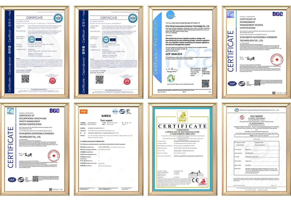
To find dependable Ceramic Pressure Sensors suppliers, you need to look at their production skills, quality certifications, and expert help resources. Certifications like ISO9001 and IATF16949 show that a process is controlled and that a car quality system is followed. For example, ATEX certifications for explosive environments and UL certifications for electricity safety meet the needs of particular applications.
As global shocks made single-source weaknesses more obvious, supply chain resiliency became more important. More reliable deliveries come from suppliers who make everything themselves, from the ceramic substrates to the final assembly and calibration. Programs that show lead times and keep extra supplies on hand protect against production stops that stop assembly lines.
Customization and Engineering Support
Standard catalogue Ceramic Pressure Sensors can be used for a lot of different tasks, but custom solutions are better for speed and interaction. Pressure port designs, electrical connectors, and mounting arrangements can be changed to fit the needs of the application. Customising the output signal, such as using amplified voltage or current loop forms, gets rid of the need for external signal processing.
Misapplications that cost a lot of money can be avoided with engineering help during the design phase. In addition to standard calibration, temperature correction formulas that are made to fit particular working conditions make the accuracy even better. Before committing to production, we work with customers to make sure that the Ceramic Pressure Sensors work properly by trying them in environments that are similar to how they will be used in real life.
Cost-Benefit Analysis and ROI
Total cost of ownership estimates show that Ceramic Pressure Sensors are more cost-effective than other types of sensors, even though they cost more to buy at first. Longer service life lowers the cost of new parts and the labour needed to install them. Less unplanned downtime that messes up production plans and hurts customer trust is caused by more reliable systems.
Generator set makers who make backup power systems for hospitals and data centers put a lot of value on how reliable sensors are. If one Ceramic Pressure Sensors unit fails during an emergency operation, the company could be held responsible for a lot more than the cost of the sensor. Ceramic Pressure Sensors technology's proven longevity lowers risk in mission-critical settings, making the higher price well worth it.
Optimizing the Use and Maintenance of Ceramic Pressure Sensors at High Temperatures
Installation Best Practices
When Ceramic Pressure Sensors are installed correctly, they last longer and give more accurate readings. When installing a pressure port, the threads must be properly engaged without being overtightened, which could cause the ceramic to break. Depending on the size of the port, torque standards are usually between 20 and 30 Nm. The choice of thread sealant affects both heat stability and pressure sealing.
It's important to pay attention to how the wires are routed so that mechanical stress and electromagnetic interference don't happen. In places with strong electricity, shielded cable that is properly grounded reduces the amount of noise that can be picked up. The way the connectors are arranged should let water drain away instead of collecting at the electrical contact, which is where rust starts.
As part of thermal management, you should avoid direct contact with radiating heat sources and make sure there is enough air flow. Even though Ceramic Pressure Sensors can work in high temperatures, keeping them working at the lower end of their temperature range makes the time between calibrations longer. When the installation geometry allows it, thermal barriers and heat sinks keep temperatures down.
Calibration and Maintenance Schedules
Intervals for calibration testing balance the need for accurate measurements with the cost of upkeep. Calibration checks may need to be done every year for critical emission control applications, but every 24 to 36 months for less demanding applications. Using movable calibrators to check the calibration on-site cuts down on downtime compared to taking the Ceramic Pressure Sensors out and recalibrating them in a lab.
Drift monitoring, which involves comparing measurements on a regular basis to reference standards, finds small changes in accuracy before they get too high. Trends in Ceramic Pressure Sensors output that show when something is getting close to its end of life are tracked by automated data logging systems. Unexpected failures that threaten process control can be avoided by replacing parts before they break down.
Troubleshooting Common Issues
A thorough diagnosis is needed to find the root reasons of output signal problems. Zero offset changes usually mean that the pressure port is blocked or the diaphragm is dirty, not that the Ceramic Pressure Sensors has failed. Using suitable solvents in flushing processes restores performance without having to pay for repair. Any changes in the span indicate that the calibration has shifted, which could mean that the Ceramic Pressure Sensors needs to be replaced or re-calibrated.
When there are electrical problems, readings become erratic or the signal goes away completely. If you look at a connector, you might find corrosion, water getting in, or broken contacts that can be fixed by cleaning the connector or getting a new one. Cable continuity checks separate wiring problems from Ceramic Pressure Sensors problems so that sensors don't need to be replaced when they're not needed.
Conclusion
For high-temperature industrial uses that require accuracy, dependability, and longevity over time, Ceramic Pressure Sensors are the best technology. The natural benefits of alumina ceramic construction—its ability to stay stable at high temperatures, prevent corrosion, and be strong mechanically—address problems that plague current sensor technologies. When you specify, install, and maintain something correctly, you get the most out of your investment because the product lasts longer and costs less to own overall.
When making purchasing choices, it's helpful to look at all of the technical needs, the supplier's skills, and the cost over the whole lifecycle. The QS-P105 type is an example of cutting-edge Ceramic Pressure Sensors technology that was made to meet the tough needs of emission control systems, power generation, and heavy machines. Strategic relationships with experienced suppliers give you access to technical help and customisation options that make Ceramic Pressure Sensors integration go more smoothly.
FAQ
What temperature range can ceramic pressure sensors reliably operate within?
Industrial Ceramic Pressure Sensors usually work continuously from -40°C to 135°C, but some special models can go up to 150°C. The QS-P105 model stays accurate within its -40°C to 135°C temperature range. Higher temperatures for short periods of time during thermal cycling or process upsets usually don't do any lasting damage. However, running above stated limits for a long time speeds up drift and shortens service life.
How do ceramic sensors compare to silicon sensors for diesel engine applications?
Ceramic Pressure Sensors work better than silicon sensors in diesel engine environments because they can handle higher temperatures and chemicals better. Silicon sensors can only work at temperatures up to 125°C, which is too hot for mounting sites in exhaust systems. Alumina ceramic doesn't rust and can handle acidic condensates and particles that break down silicon. Different prices are caused by changes in the cost of materials, but longer repair periods make Ceramic Pressure Sensors technology more cost-effective overall.
Can ceramic pressure sensors be customized for specific applications?
Pressure port configurations, electrical connectors, mounting brackets, pressure ranges, and output signal formats are all things that can be changed to make the Ceramic Pressure Sensors unique. For better accuracy, temperature compensation settings can be changed to fit different working situations. Depending on how complicated the change is, the minimum order quantity for unique Ceramic Pressure Sensors specs is usually between 100 and 500 units. During the design process, we work with customers to make sure that the Ceramic Pressure Sensors specifications meet their particular needs while still being cost-effective.
Partner with a Trusted Ceramic Pressure Sensor Manufacturer
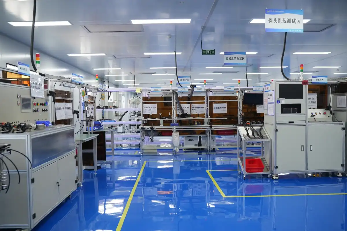
Qintai makes Ceramic Pressure Sensors that are industrial-grade and designed for the toughest high-temperature uses. As China's top original equipment manufacturer (OEM) provider to major diesel engine makers like Weichai, Yuchai, and Quanchai, we have over 20 years of experience in emission control and a long list of certifications. Our QS-P105 Ceramic Pressure Sensors are accurate, resistant to heat, and long-lasting, which are all things that your important systems need.
We help you reach your procurement goals by offering flexible customisation, quick technical collaboration, and competitive pricing for large orders. Our dedication to quality is shown by our ISO9001, IATF16949, and other foreign safety certificates. Together with your technical staff, our experienced engineering team comes up with the best Ceramic Pressure Sensors configurations that balance performance and cost-effectiveness. Contact info@qt-sensor.com to talk about your Ceramic Pressure Sensors needs with application experts who are ready to help you succeed.
References
1. Webster, J.G., & Eren, H. (2018). Measurement, Instrumentation, and Sensors Handbook: Spatial, Mechanical, Thermal, and Radiation Measurement. CRC Press.
2. Tian, B., Zhao, Y., Jiang, Z., & Hu, B. (2017). The Development of Key Technologies in Applications of Vessels. Singapore: Springer Nature.
3. Norton, H.N. (1989). Handbook of Transducers. Englewood Cliffs: Prentice Hall.
4. Bau, H.H., de Rooij, N.F., & Kloeck, B. (1994). Mechanical Sensors (Sensors: A Comprehensive Survey Vol. 7). Weinheim: VCH Publishers.
5. Chiou, J.A., & Chen, S. (2008). Thermal hysteresis analysis of ceramic pressure sensors. Sensors and Actuators A: Physical, 147(2), 580-585.
6. Keil, S. (2017). Technology and Practical Use of Strain Gages: With Particular Consideration of Stress Analysis Using Strain Gages. Berlin: Wilhelm Ernst & Sohn.


Our customers’ satisfaction speaks for our quality — contact us to experience the same reliable service.