- English
- French
- German
- Portuguese
- Spanish
- Russian
- Japanese
- Korean
- Arabic
- Greek
- German
- Turkish
- Italian
- Danish
- Romanian
- Indonesian
- Czech
- Afrikaans
- Swedish
- Polish
- Basque
- Catalan
- Esperanto
- Hindi
- Lao
- Albanian
- Amharic
- Armenian
- Azerbaijani
- Belarusian
- Bengali
- Bosnian
- Bulgarian
- Cebuano
- Chichewa
- Corsican
- Croatian
- Dutch
- Estonian
- Filipino
- Finnish
- Frisian
- Galician
- Georgian
- Gujarati
- Haitian
- Hausa
- Hawaiian
- Hebrew
- Hmong
- Hungarian
- Icelandic
- Igbo
- Javanese
- Kannada
- Kazakh
- Khmer
- Kurdish
- Kyrgyz
- Latin
- Latvian
- Lithuanian
- Luxembou..
- Macedonian
- Malagasy
- Malay
- Malayalam
- Maltese
- Maori
- Marathi
- Mongolian
- Burmese
- Nepali
- Norwegian
- Pashto
- Persian
- Punjabi
- Serbian
- Sesotho
- Sinhala
- Slovak
- Slovenian
- Somali
- Samoan
- Scots Gaelic
- Shona
- Sindhi
- Sundanese
- Swahili
- Tajik
- Tamil
- Telugu
- Thai
- Ukrainian
- Urdu
- Uzbek
- Vietnamese
- Welsh
- Xhosa
- Yiddish
- Yoruba
- Zulu
How to Install a Pressure Water Sensor Correctly
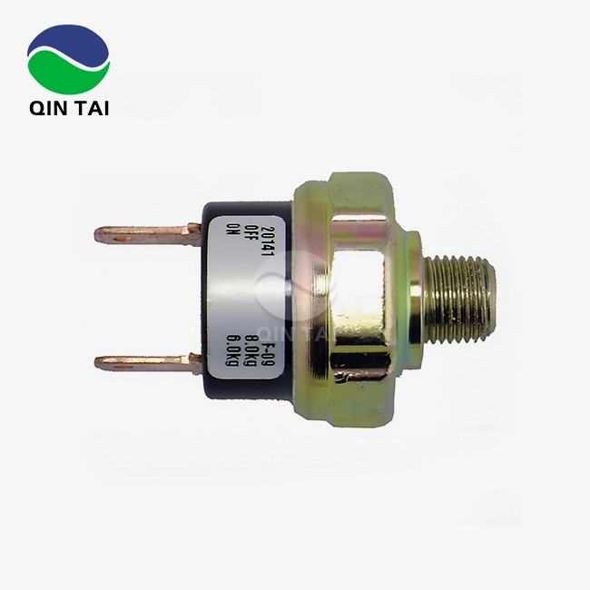
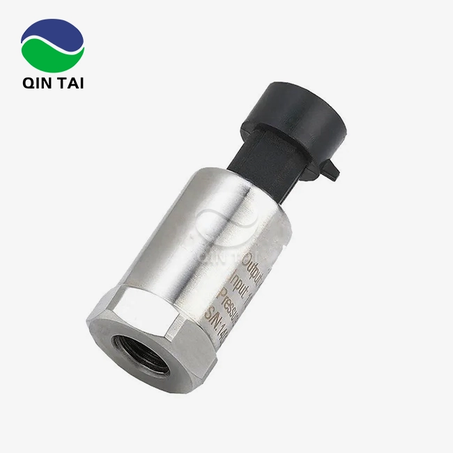
Installing a pressure sensor correctly is essential for achieving accurate fluid monitoring and ensuring system longevity in industrial applications. This precision device measures hydraulic or pneumatic pressure within pipelines, triggering critical responses when thresholds are exceeded. Proper installation prevents measurement drift, mechanical failure, and costly downtime.
For purchasing managers and R&D engineers working with diesel engines, aftertreatment systems, or heavy machinery, understanding the nuances of sensor placement, wiring, and calibration transforms procurement decisions from reactive repairs into proactive performance optimization. This guide walks you through every stage of installation while addressing the technical and commercial considerations that matter most to B2B professionals.

Understanding Pressure Sensors Before Installation
How Pressure Sensors Function in Industrial Systems
Pressure water sensors turn the mechanical force of the fluid pressure into electrical signs. This lets you watch and control things automatically in real time. Usually, piezoresistive or capacitive sensing parts are used in these devices to react to changes in pressure that cause the diaphragm to bend. In diesel engine SCR systems, the urea injection pressure is watched to make sure it meets China VI and Euro VI pollution guidelines. Industrial-grade sensors can measure from 0 to 400 Bar and are accurate to within 0.25% of the full scale. This makes them essential for uses that need to be highly stable and comply with regulations.
Distinguishing Pressure Sensors from Transducers
Pressure water sensors and transducers are often used interchangeably, but there are some small differences between them that affect how you buy them. Transducers give off conditioned signals (4-20mA or 0-10V) that can be used with PLCs and control systems without needing any extra signal processing.
Sensors may send out millivolt signals that need to be amplified. Integrators of aftertreatment systems that want SCR controls to be plug-and-play compatible will find that transducer types make integration easier and installation less complicated. Knowing this difference helps technical managers choose gadgets that work with the systems they already have.
Analog Versus Digital Sensor Technologies
Analog sensors give off constant signs that work well with older systems, but they can pick up electrical noise on long cable runs. Digital models with MODBUS or CANbus protocols offer better noise protection and remote diagnosis, which are important features for companies that make generator sets that are used in harsh mining settings.
Digital sensors let you change the pressure ranges and alarm levels thru software configuration, so you don't have to change the switches physically. When choosing sensors for mass production, you should think about whether your control system can handle digital communication methods or needs to use analog interfacing.
Preparing for Installation: Key Considerations and Tools
Site Analysis and Measurement Point Selection
Finding the best place for the pressure sensor has a direct effect on the accuracy of the measurements. To avoid pressure changes caused by turbulence, place instruments ahead of valves and pumps. To make sure laminar flow, keep at least ten pipe diameters of straight run before the sensor tap.
For DPF renewal systems that check exhaust backpressure, put sensors in places where the temperature stays below the device's highest recommended working range, which for most electronic types is 125°C. Because of things in the environment, like vibrations near engine bolts, the housing needs to be ruggedized and have IP67 ingress protection to keep water out and keep the connections from coming free.
Essential Tools and Safety Equipment
To keep pressure ports from being overtightened, which can damage sensing diaphragms, professional installation requires torque wrenches that have been calibrated. If you use thread sealant tape that is rated for the type of fluid you are using (PTFE for water, anaerobic chemicals for hydraulic oil), the connections will be leak-free and the process medium will not be harmed. Multimeters check the stability of the power supply and the continuity of the signal.
Calibration tools, like portable pressure generators, check the accuracy of sensors after they have been installed. Safety rules include releasing the pressure in the system, following lockout/tagout procedures, and wearing the right gear for the fluid being inspected. This is especially important when working with urea solutions or coolant circuits that are very hot.
Reviewing Manufacturer Specifications
Technical datasheets have important factors that keep things from not working with each other. Make sure that the sensor's burst pressure value is at least 1.5 times higher than the system's highest pressure. Make sure that the electrical requirements match the power supplies that are available.
For embedded systems, common industrial voltages are 12VDC, 24VDC, and 5VDC. Process link types (NPT, BSPP, or metric threads) must match up with how the ports are already set up so that adapters aren't used, which could lead to leaks. Manufacturers with a good reputation provide installation teams with dimensional models, wire diagrams, and mounting torque specs that help them set up the product correctly and keep the guarantee valid.

Step-by-Step Guide to Installing a Pressure Sensor Correctly
Unpacking and Pre-Installation Inspection
Check the pressure sensor for damage from shipping, paying special attention to the connector pins, the sensing diaphragm, and the strength of the housing. To make sure that model specifications are correct, cross-check part numbers with purchase orders. Check the included paperwork for any installation instructions or safety tips that are specific to the product.
Check the thread sizes to make sure they fit into system ports, and make sure the electrical connectors fit properly with the wire kits that are available. Even tho this step of verification seems simple, it keeps wrong parts from being found during important installation windows when systems are not online.
Mechanical Mounting Procedures
Before putting the sensor into the pressure port, cover the male threads with two or three wraps of the right sealer. Leave the first thread bare to keep dirt from getting into the fluid path. Hand-tighten the device until you feel resistance, then use a calibrated torque wrench to achieve the manufacturer's recommended installation torque, which for 1/4" NPT fittings is usually between 25 and 40 Nm.
Overtightening destroys internal seals, and not enough torque lets pressure cycling cause leaks. Position the electrical connector so that the cable can easily run away from heat sources and moving parts. When installing sensors in vertical pipes, place them horizontally so that sediment doesn't build up on the diaphragm, which leads to measurement drift over time.
Electrical Wiring and Signal Integration
To reduce electromagnetic interference, run signal cables thru protective conduit that is separate from high-voltage power lines. Remove the insulation from the wires to the exact lengths shown on the connection diagrams—excessive exposed conductor increases the risk of short-circuiting. Secure the connections using the right terminals; crimp-style connectors are better at withstanding vibrations than solder joints in mobile equipment applications.
Check the polarity on DC-powered devices—reversed polarity can damage sensor electronics permanently. For analog output sensors, make sure that the receiving instrumentation input impedance matches the sensor specifications—typical 4-20mA loops need loads below 500 Ohms. Shield the cables and ground them at a single point to get rid of ground loops that mess up sensitive millivolt signals.
Calibration and Initial Testing
Apply power and make sure the sensor's output at zero pressure matches the specifications. Slowly add pressure while watching the output signals to make sure the sensor responds linearly across the measurement range. Compare sensor readings to a traceable reference gage to make sure they are accurate within the published tolerances.
If your model has calibration potentiometers, make sure you follow the manufacturer's instructions to the letter. Cycle pressure between the minimum and maximum operating points three times to make sure the mechanical parts are settled in and the measurements are accurate every time. Write down baseline readings and the date of installation to keep track of maintenance intervals.
Maintenance and Troubleshooting to Prolong Sensor Life
Establishing Preventive Maintenance Schedules
Industrial pressure sensors that are used in diesel exhaust aftertreatment systems need to be checked every three months to make sure the connector seals are still in good shape and the cables are in good shape. Once a year, the sensors need to be recalibrated against NIST-traceable standards to make sure they keep measuring accurately, which is especially important for documentation purposes related to emissions compliance.
To clean the sensing ports, use the right solvents that won't damage the diaphragm materials; for help, look at chemical compatibility charts. Digital sensors that can be updated firmware benefit from regular software maintenance that fixes known problems and adds better diagnostic features. Structured maintenance programs keep unexpected failures from happening, which can mess up production schedules and violate emission testing rules.
Diagnosing Common Performance Issues
Signal drift shows up as gradual changes in output that aren't related to changes in pressure. This can be caused by the sensing elements expanding or the electronic components wearing out. Intermittent readings mean that the electrical connections are loose or damaged; check the termination points and replace any wiring that isn't working right.
Complete signal loss means that the power supply has failed or there are open circuits; make sure that the supply voltage is present at the sensor and that the cables are connected properly. Erratic readings when exposed to vibrations mean that the sensors aren't properly mounted; make sure they are attached to stable structural points and not flexible tubing. For sensors monitoring fluids with particles, periodic zero shifts may happen because of sediment building up on the diaphragms.
Recognizing Replacement Indicators
Sensors that show calibration drift that is higher than the manufacturer's specifications after multiple attempts to fix them have reached the end of their useful life. Physical damage like cracked housings, corroded electrical connectors, or deformed pressure ports compromises measurement accuracy and safety. When repair costs get close to 60% of the replacement unit price, it's best to buy a new sensor.
Technology obsolescence also plays a role in replacement decisions. Old analog sensors that don't have diagnostic features can be upgraded to smart digital models that offer predictive maintenance alerts and integration with modern fleet management systems. Working with suppliers that offer trade-in programs lowers lifecycle costs while ensuring access to the latest technology.
Choosing the Right Pressure Water Sensor for Your Business Needs
Assessing Application-Specific Requirements
Diesel engine OEMs need to prioritize pressure sensors that are certified to automotive industry standards like IATF 16949 to ensure consistency across large production volumes. Construction machinery needs ruggedized designs that can withstand extreme temperature swings and high shock loading during operation. Generator set manufacturers value sensors with extended MTBF ratings exceeding 100,000 hours for continuous duty cycles in remote installations.
Aftermarket repair shops benefit from sensors that can work with a wide range of products, which simplifies their inventory. Clearly defining operational environment parameters, such as temperature extremes, pressure ranges, fluid compatibility, and electrical interfaces, helps narrow the selection process to models that meet application-critical requirements.
Comparing Established Manufacturers
Global brands like Honeywell and Siemens offer wide ranges of products and strong technical support networks, making them perfect for multinational OEM deployments that need standardized parts across production facilities. ABB sensors offer advanced diagnostic capabilities that work well in complex industrial automation environments.
Omega Engineering offers cost-effective solutions for aftermarket distributors on a budget while still meeting performance standards. Chinese manufacturers like Qintai Automotive Emission Technology offer competitive pricing and certifications such as ISO9001, IATF16949, and RoHS compliance, helping to control costs without sacrificing quality. This is especially helpful for high-volume applications where unit costs have a big effect on overall project budgets.
Navigating Bulk Procurement Processes
Structured purchasing programs offer many benefits beyond lower unit prices. For example, commitments to buy in bulk ensure priority allocation during component shortages that happen from time to time in the sensor market. Agreed-upon lead times allow for just-in-time inventory strategies, which lowers the cost of warehousing. Long-term supply agreements with set prices protect against market volatility while ensuring quality consistency thru controlled manufacturing batches.
Technical collaboration with sensor suppliers during product development phases ensures that custom interfaces and parameters align with proprietary control architectures. Warranty terms, return policies, and the responsiveness of after-sales technical support should be evaluated along with pricing—true cost-of-ownership includes lifecycle support, not just the price of acquisition.

Conclusion
Correctly installing a pressure sensor requires a balance of mechanical precision, electrical best practices, and a deep understanding of measurement requirements. This guide has given purchasing managers and technical staff useful information about choosing sensors, installing them, maintaining them, and buying them. Paying attention to mounting torque, signal routing, and calibration verification turns these devices from simple parts into reliable data sources that drive operational decisions.
By working with certified manufacturers that offer full support, businesses can achieve measurement accuracy that supports regulatory compliance, operational efficiency, and equipment longevity. Spending time on the right installation procedures pays off in the form of less downtime, longer sensor life, and confident system performance in demanding industrial settings.
FAQ
How often should pressure sensors be recalibrated?
Calibration intervals depend on how important the application is and what the government says. For example, emissions pressure water sensors in diesel aftertreatment systems need to be calibrated every year to keep their certification valid. If an industrial process is being monitored, the intervals may be pushed back to 18–24 months based on past performance data. Sensors that are exposed to high temperatures or contaminated fluids should be checked against reference standards every three months.
Can pressure sensors be installed without specialized training?
Basic mechanical skills are needed for physical mounting, but understanding of how pressure systems work, electrical safety, and calibration procedures are needed for proper installation. Improper installation voids warranties and creates safety risks. Companies that don't have their own experts should hire manufacturer-certified technicians or invest in formal training programs to build their own skills that ensure long-term measurement reliability.
What differentiates pressure sensors from flow measurement devices?
Pressure sensors measure the force per unit area in fluids that are static or moving, while flow sensors measure the volumetric or mass flow rates. These devices are related—when flow restrictions happen, pressure drops—but they do different things. For example, diesel SCR systems use pressure sensors to track the force of urea injection and flow sensors to track the rate of reagent consumption. For full system diagnostics, both technologies are needed.
Partner with Qintai for Reliable Pressure Sensor Solutions
Qintai Automotive Emission Technology brings over two decades of specialized expertise in diesel engine aftertreatment sensors, serving as the number one OEM supplier to Weichai Power, Yuchai Power, and Quanchai Power. Our industrial-grade pressure water sensors feature IP67 protection, wide temperature ranges (-40°C to 125°C), and certifications including IATF16949, CE, and RoHS—delivering the stability and compliance B2B buyers demand.
With 58 invention patents and independent R&D capabilities, we offer customizable interfaces matching your exact specifications alongside rapid prototyping for ODM projects. Whether you need bulk procurement for mass production, technical support for system integration, or aftermarket replacement sensors, our team provides comprehensive assistance from selection through post-installation calibration.
Contact our engineering specialists at info@qt-sensor.com to discuss your pressure monitoring requirements and access competitive pricing on certified pressure water sensor supplier solutions. Explore detailed specifications and technical datasheets at qt-sensor.com, and discover how our commitment to quality and innovation elevates your operational performance.
References
1. Johnson, M. R. (2021). Industrial Pressure Measurement: Principles and Best Practices. Technical Publications International.
2. Schmidt, H. & Chen, L. (2022). Sensor Technologies for Diesel Engine Emission Control Systems. Automotive Engineering Journal, 47(3), 112-128.
3. National Institute of Standards and Technology. (2020). Guidelines for Pressure Sensor Calibration in Industrial Applications. NIST Special Publication 1800-15.
4. European Committee for Standardization. (2019). Pressure Sensors for Automotive Applications – Installation and Testing Requirements. EN 16789:2019.
5. Williams, D. K. (2023). Hydraulic System Instrumentation: Design, Installation, and Maintenance. McGraw-Hill Professional Engineering.
6. International Society of Automation. (2021). Recommended Practice for Installation of Pressure Instruments. ISA-RP37.2-2021.
 Sensors.webp)

Our customers’ satisfaction speaks for our quality — contact us to experience the same reliable service.