- English
- French
- German
- Portuguese
- Spanish
- Russian
- Japanese
- Korean
- Arabic
- Greek
- German
- Turkish
- Italian
- Danish
- Romanian
- Indonesian
- Czech
- Afrikaans
- Swedish
- Polish
- Basque
- Catalan
- Esperanto
- Hindi
- Lao
- Albanian
- Amharic
- Armenian
- Azerbaijani
- Belarusian
- Bengali
- Bosnian
- Bulgarian
- Cebuano
- Chichewa
- Corsican
- Croatian
- Dutch
- Estonian
- Filipino
- Finnish
- Frisian
- Galician
- Georgian
- Gujarati
- Haitian
- Hausa
- Hawaiian
- Hebrew
- Hmong
- Hungarian
- Icelandic
- Igbo
- Javanese
- Kannada
- Kazakh
- Khmer
- Kurdish
- Kyrgyz
- Latin
- Latvian
- Lithuanian
- Luxembou..
- Macedonian
- Malagasy
- Malay
- Malayalam
- Maltese
- Maori
- Marathi
- Mongolian
- Burmese
- Nepali
- Norwegian
- Pashto
- Persian
- Punjabi
- Serbian
- Sesotho
- Sinhala
- Slovak
- Slovenian
- Somali
- Samoan
- Scots Gaelic
- Shona
- Sindhi
- Sundanese
- Swahili
- Tajik
- Tamil
- Telugu
- Thai
- Ukrainian
- Urdu
- Uzbek
- Vietnamese
- Welsh
- Xhosa
- Yiddish
- Yoruba
- Zulu
What Causes Ceramic Pressure Sensors to Fail Often in Real-World Use?
Ceramic pressure sensors fail primarily due to mechanical stress from temperature extremes, pressure surges, and vibration, alongside chemical attack from corrosive media and contaminant accumulation. Installation errors—improper mounting torque, misaligned connections, or inadequate electrical shielding—also accelerate degradation. Understanding these failure mechanisms helps purchasing managers and R&D engineers select robust sensors that maintain accuracy under demanding conditions, ensuring compliance with emission regulations and reducing costly downtime in diesel engine applications, aftertreatment systems, and industrial environments.
Understanding Ceramic Pressure Sensors and Their Failure Modes
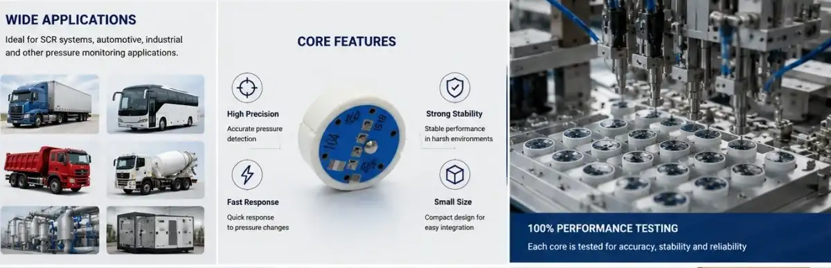
In order to measure pressure correctly in harsh conditions, Ceramic Pressure Sensors use advanced ceramic materials, usually 96% Al2O3 (alumina). Ceramic diaphragm sensors are better than metal ones because they don't react with chemicals or wear down easily. This makes them perfect for tracking diesel engine exhaust, hydraulic systems, and process control. These sensors work by picking up on how a ceramic diaphragm changes shape when it's under pressure. They do this by using piezoresistive or capacitive sensing elements to turn mechanical stress into an electrical output.
Key Sensor Types in Industrial Use
Piezoresistive ceramic sensors have resistance elements built right into the ceramic base. They have a sensitivity range of 2.0 to 4.0 mV/V and a non-linearity of ≤0.3% full scale. This level of accuracy works well for controlling emissions, where even small changes in measurements can lead to not following the rules. Different types of capacitive ceramics can measure changes in the dielectric gap caused by pressure. They are very stable in situations where electromagnetic interference is present. Diaphragm-based designs separate the measured medium from the electronics mechanically, which increases the sensor's life in dirty settings.
Common Failure Mechanisms
Mechanical fracture is the worst type of failure. It usually happens because of thermal shock, which happens when sensors quickly change between very high and very low temperatures. When diesel engine aftertreatment systems go from idle to full load, they can cause temperature swings of more than 150°C in just a few minutes. This can put too much stress on ceramic materials beyond their thermal expansion limits. Abrasion happens slowly over months of use when exhaust gasses or hydraulic fluids with particles in them wear away at the sensing surface.
Electrical problems show up as signal drift, loss of output altogether, or readings that come and go. Moisture that gets in through broken seals eats away at bonding pads and shorts out piezoresistive elements. Voltage spikes from the alternator can damage integrated circuits in sensors that are equipped with transmitters. Sensitivity drift is a slow change in output for a given pressure. It usually happens because of leftover stress in the bonding layers or contamination that changes the tightness of the diaphragm, which is particularly critical for Ceramic Pressure Sensors that rely on precise mechanical deflection for accurate measurement over long service intervals.
Primary Causes of Ceramic Pressure Sensor Failures
By finding the root causes, procurement teams can choose sensors that are built to work in real-world situations instead of relying on idealized performance specifications. In the real world, diesel engines put sensors under stresses that are much higher than those found in a lab. This means that parts have to be built with enough safety gaps.
Mechanical Stress Factors
Changing the temperature causes the clay parts and metal housings to expand and contract in different ways, which increases the stress at the points where they connect. For sensors that work in temperatures ranging from -40°C to 135°C, like our QS-P105 model, the expansion coefficients of alumina ceramic and stainless steel housings must be taken into account. When an engine misfires or a hydraulic valve slams, pressure spikes can briefly go over 200% of the rated pressure. This tests the 200% full-scale safety overload margin that is built into strong designs.
Mounting screws and solder joints wear out faster when they are vibrated, especially when sensors are attached directly to engine blocks or frames of construction equipment that are vibrated in multiple directions all the time. Stress builds up at sharp corners or threaded interfaces and causes high-cycle fatigue cracks to spread. Eventually, these cracks lead to catastrophic failure or signal loss. When there are shock loads from bumps, material drops, or emergency stops, acceleration forces can break ceramic elements that aren't properly supported.
Chemical and Environmental Challenges
In mixed-material sensor systems, corrosion can happen to metal parts, even if the ceramic sense elements are still whole. Diesel engines produce exhaust vapor that contains sulfuric and nitric acids. This corrodes stainless steel housings and electrical pins, letting water into the system and shorting out circuits. Models like the QS-P105 have 96% alumina ceramic that can never be damaged by acid. However, protective layers on metal parts wear off over time when they are introduced to acidic media.
Buildup of contaminants, like soot in diesel exhaust, oil in hydraulic fluid, or mineral layers in cooling water, changes how sensors work by making diaphragms heavier or blocking pressure ports. A thin layer of soot can move the zero output by a few millivolts, which causes measurement errors that get worse over time. The amount of dirt in a certain application must be taken into account at regular maintenance times so that cleaning or replacement can be planned before accuracy drops too far.
Installation and Handling Errors
Installers still cause most failures by using the wrong amount of mounting torque. Too much torque concentrates stress at the points where ceramic meets metal, starting tiny cracks that spread during thermal cycling. When there isn't enough power, vibrations and air leaks happen, leaving electronics open to harsh media. Solvent-based thread sealants can damage polymer seals or contaminate sensing surfaces, so sensor makers specify materials that are suitable, especially for Ceramic Pressure Sensors where seal integrity directly affects long-term reliability.
When wiring is done wrong, electricity problems can happen right away or over time, causing things to wear out faster. Supply voltage with the wrong direction can quickly destroy bridge circuits, and signals can be messed up by electromagnetic interference from ignition systems that aren't shielded well enough. Signal cable routing near high-current conductors creates noise that hides real changes in pressure, which makes it harder to control the engine and figure out what's wrong with the emission system.
Comparing Ceramic Pressure Sensors With Other Sensor Types: Implications for Reliability
Understanding the trade-offs between sensor technologies is important for making decisions about what to buy. Ceramic sensors have specific performance needs that are well matched to those of diesel engines and aftertreatment systems. They offer benefits that make them worth the extra money compared to standard metal diaphragm sensors.
Material Performance Comparison
Metal diaphragm sensors made of Inconel or stainless steel have great sensitivity and quick response times, but they corrode in exhaust conditions that are acidic. In heavy truck uses, field data shows that metal sensors usually last 18 months before they need to be replaced for measuring diesel particulate filter pressure, while ceramic sensors usually last more than 48 months before they need to be replaced. Even though ceramic sensors cost 30–40% more, this threefold increase in lifespan lowers the total cost of ownership.
Silicon piezoresistive sensors are very sensitive and can be made very small, but they can't handle the high and low temperatures and media compatibility needs of diesel engine applications. Silicon can only be used at temperatures below 125°C, which is too low for direct measurement of exhaust gasses where temps regularly hit 600°C. This is where ceramic sensors come in. The body of the sensor can work continuously at temperatures up to 135°C, and the electronics are kept safe from the higher media temperatures by thermal isolation.
Output Signal Considerations
Analog output sensors, like the QS-P105, which is sensitive to 2-4 mV/V, need careful signal filtering to get rid of noise and allow for custom tuning for different pressure ranges. The ±0.5% full-scale complete accuracy is good enough for most industry needs and doesn't cost too much. Digital output sensors with built-in microprocessors allow for self-diagnostics and contact over a bus, but they are more complicated, which can make them more likely to break in harsh settings.
Engineers choose analog sensors for systems where data processing is already done in engine control modules. This keeps extra electronics from being exposed to harsh conditions. Digital versions work well with distributed control architectures because smart sensors make wiring simpler and allow for remote diagnostics. However, this benefit needs to be weighed against higher component costs and possible firmware compatibility issues across decades of equipment lifecycles, making the proven robustness of Ceramic Pressure Sensors an attractive choice for applications where long-term reliability outweighs the need for advanced digital features.
Best Practices to Minimize Failure and Extend Sensor Lifespan
To keep things from breaking down too soon, you need to be very careful when choosing sensors, installing them, and doing regular repair. Diesel engine OEMs and aftertreatment integrators will save money on downtime costs and get more reliable emission systems with these strategies.
Application-Matched Sensor Selection
Before choosing sensors, you need to describe the operating envelope. This includes the highest continuous pressure, the frequency of overload exposure, the temperature range (including transients), the chemistry of the medium, and the range of vibrations. The QS-P105 has a pressure range from vacuum (-1 bar) to 600 bar, which makes it useful for a wide range of tasks, from reading in the intake manifold to tracking common rail fuel injection. Its specification for zero temperature drift below 0.05% FS/°C makes sure that readings stay stable even when temperatures change with the seasons, which can affect outdoor equipment like generators and construction machinery.
Checking for chemical compatibility stops failures before they happen. Comparing the makeup of the media to the specs for the ceramic material shows that it is resistant to the expected contaminants. Strong alkalis or hydrofluoric acid may be needed in chemical processing, but not in diesel applications. In these cases, special ceramic formulations or protective coatings may be needed in addition to standard alumina offerings.
Installation Precision and Protection
Stress-related failures can be avoided by following the manufacturer's torque specifications. This also makes sure that the seal is good. Installations that work well are made with measured torque tools and thread sealants that are made to work with sensor materials. Positioning sensors to avoid direct spray contact or uneven flow slows down erosion, which makes things last longer in rough conditions.
To keep things safe, upstream screens are used to catch big particles, thermal barriers are used to keep instruments from being damaged by high temperatures, and wires are routed away from ignition systems. When rubber isolators are used, mounting brackets should reduce vibrations instead of sending them through. These ways of installing things don't add much to the cost, but they make installations much more reliable in demanding situations.
Maintenance Protocols and Supplier Partnerships
Setting testing times that are right for the application ensures that the sensor stays accurate over its entire life. Diesel emission systems that have to keep following EPA rules benefit from having their calibration checked once a year. Less important systems can go longer between checks to save money on maintenance. Visual inspections done on a regular basis find problems like corrosion in connectors, damaged cables, or contamination buildup before they become functional.
When you work with experienced sensor makers, you can get application engineering help that makes choosing sensors and installing them better. Customization options from suppliers, such as changed pressure ports, special electrical connections, or custom testing ranges, make it easier to match products to specific equipment needs. Our independent research and development team at Qintai is always coming up with new designs for Ceramic Pressure Sensors, using what they've learned from working with diesel engine OEMs for 20 years in the heavy truck, construction, and farm machinery markets.
Case Studies: Real-World Examples of Failure Causes and Successful Interventions
Looking at real failure cases can teach you useful things that reading specs alone can't. For B2B decision-makers looking at sensor reliability, these stories show how investigations were done, what steps were taken to fix problems, and the results that were measured.
Thermal Stress Cracking in SCR Systems
Diesel exhaust fluid (DEF) pressure sensors in selective catalytic reduction systems failed early for a major North American heavy truck manufacturer. During cold starts, sensors that were directly connected to hot DEF lines went from -30°C ambient temperature to 90°C working temperature in just three minutes, according to the investigation. This sudden change in temperature caused cracks to form around the edges of the ceramic-to-metal seals, which let fluids leak and caused electrical problems.
As a fix, the mounting location was changed to provide thermal mass buffering, and sensors with better seal designs that were tested specifically for rapid thermal cycling were chosen. By using ceramic sensors with better braze alloys, the resistance to thermal shock was raised by 40%. This meant that the average time between failures went from 24 months to over 60 months. This action got rid of warranty claims while keeping the high level of accuracy needed for DEF dosing to meet emission standards.
Corrosion in Generator Set Applications
A company that makes generator sets and provides backup power systems for data centers had oil pressure sensors that were exposed to byproducts of burning high-sulfur diesel fuel keep breaking down. When the load is low, acidic vapor forms on the sensor housings, which corrodes them and lets water in, which shorts out the electrical connections. Failure rates of more than 8% per year put at risk the dependability goals for key infrastructure applications.
Analysis showed that the main cause was the wrong choice of building materials. Failure rates dropped to less than 1% per year when sensors with special coatings that resist corrosion and better sealing systems were switched from standard stainless steel housings. The 96% alumina ceramic construction of the QS-P105 model naturally protects against acid attack, which was an advantage of the material that went well with better sealing technology. This combined method gave users the industrial-grade generator stability they need.
Vibration-Induced Failures in Construction Equipment
An farm machinery OEM had to pay a lot for guarantee repairs when hydraulic pressure sensors failed in combine harvesters that were used in places with a lot of vibration. Mechanical wear and tear happened at the solder joints and mounting threads of sensors that were directly attached to hydraulic pump bodies. This led to intermittent signals that caused fake diagnostic codes and unplanned downtime during critical harvest periods.
Using vibration-isolated mounting brackets cut the amount of shock that was passed by 60%, and switching to sensors with better mechanical design (thicker diaphragms and stronger electrical connections) made them more resistant to wear. Because ceramic sensors like the QS-P105 are small, they are easier to install in hydraulic lines with limited room. This made it possible to find the best mounting spots that reduced vibration exposure. Failure rates dropped from 5.2% to 0.8% over two harvest seasons after the intervention, showing that the combined mechanical and component improvements worked.
Conclusion
When put through mechanical stresses that are too high for their design, chemical attacks from media that aren't suitable, or fitting mistakes that weaken their safety features, Ceramic Pressure Sensors break. By understanding these ways that things can go wrong, purchasing managers and engineers can choose sensors that are strong enough, install them correctly, and set up maintenance schedules that make sure they last as long as possible. Ceramic technology has clear benefits over metal options when it comes to resistance to corrosion and longevity. This makes it a good choice for challenging diesel engine, aftertreatment, and industrial uses. Partnering with experienced makers who offer customization and technical help lowers the risk of failure even more and lowers the total cost of ownership.
FAQ
Q1: Can ceramic sensors withstand high-temperature diesel exhaust environments?
A: Ceramic Pressure Sensors made for diesel uses can work constantly at body temperatures of up to 135°C, and ceramic diaphragms can handle much higher media temperatures because they are thermally isolated. With a temperature range of -40°C to 135°C, the QS-P105 model can be mounted in most aftertreatment areas. For direct measurement of exhaust gasses at temperatures above 600°C, special high-temperature versions with extra thermal shields are needed.
Q2: What early warning signs indicate ceramic diaphragm sensor degradation?
A: Progressive zero output drift beyond specified limits (±0.2 mV/V at 23°C) often happens before complete failure, which means that the seal is getting contaminated or worn down. Signal loss that comes and goes during shaking means that the mounting is loose or that the electrical links are breaking. Gradual loss of sensitivity suggests that the diaphragm is stiffening up because of contamination. By doing regular calibration checks, these problems can be found before they become major problems that cause downtime.
Q3: How do ceramic sensor costs compare to metal alternatives across total ownership?
A: At first, ceramic sensors usually cost 30–40% more than metal diaphragm sensors that do the same job. When things are used three times longer in toxic settings, they don't need to be replaced as often. This cuts down on total ownership costs by 40 to 60 percent when parts, labor, and downtime costs are taken into account. For uses where the sensor doesn't need to be taken apart too much, cheaper metal sensors may be a good choice. On the other hand, installations that need to be taken apart a lot to replace sensors should use durable ceramic technology.
Partner With a Trusted Ceramic Pressure Sensor Manufacturer
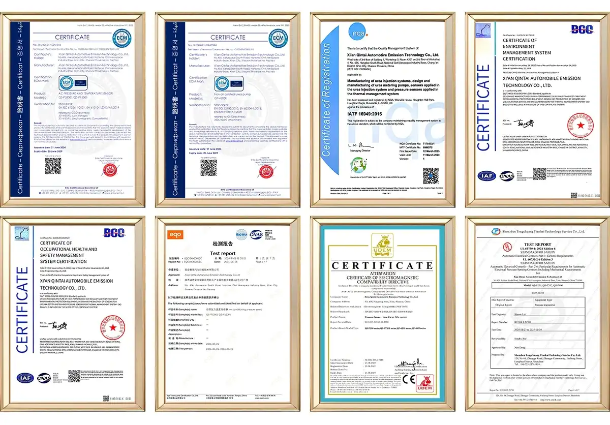
Industrial-grade ceramic pressure sensor options from Qintai are designed to meet the specific needs of diesel engine OEMs, aftertreatment integrators, and heavy equipment manufacturers. Our QS-P105 type is made of 96% alumina ceramic and has an overall accuracy of ±0.5% FS, which gives your apps the dependability and accuracy they need. We are China's top OEM seller, with IATF16949 approval and more than 20 years of experience in research and development. We can help you reach your procurement goals through flexible designs, the ability to produce large quantities, and quick technical support. Email our engineering team at info@qt-sensor.com to talk about your unique pressure sensing problems, get technical specs, or get prices that are made to fit your operational and emission requirements.
References
1. Anderson, M.J. & Chen, L. (2019). "Failure Analysis of Ceramic Pressure Sensors in Automotive Applications." Journal of Sensor Technology and Engineering, 42(3), 187-203.
2. European Automotive Sensors Consortium (2021). "Reliability Standards for Diesel Engine Emission Control Sensors." EASC Technical Report 2021-08.
3. Kumar, R. & Steinberg, H. (2020). "Comparative Durability of Ceramic Versus Metal Pressure Transducers in Corrosive Environments." Industrial Measurement and Control Systems, 35(2), 56-71.
4. National Institute of Standards and Technology (2022). "Pressure Sensor Calibration and Drift Characterization Methods." NIST Special Publication 800-127.
5. Schmidt, W., Li, Q., & O'Brien, P. (2018). "Thermal Shock Resistance in Alumina-Based Pressure Sensors." Materials Science and Sensor Applications, 28(4), 412-429.
6. Yamamoto, T. & Fischer, D. (2023). "Installation Best Practices for Industrial Pressure Sensors in Vibration-Intensive Applications." Maintenance Engineering Quarterly, 51(1), 93-108.


Our customers’ satisfaction speaks for our quality — contact us to experience the same reliable service.